Safety and reliability in home alternative-energy systems
Isolation and protection circuits keep homeowners and their equipment safe
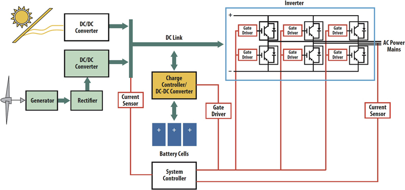
Figure 1: A typical AES design includes power sources sharing a common high-voltage DC Link, an inverter for generating AC, and a system controller ensuring coordinated operation.
Solar- and wind-power-based home AESs (alternative energy systems) are becoming more popular among consumers. To achieve the product lifetime that consumers demand and ensure user safety, system designs need built-in protections against short circuits and other failures. The power inverter and its control system are the place to focus. A home AES has several major components that must work together for optimum efficiency and lowest cost (Figure 1). The defining component is the power source. Solar panels are often equipped with an MPP (maximum power point) controller to increase efficiency. Home systems also use wind generators, both alone and to supplement solar panels as primary power sources. Battery banks commonly serve in combination with solar panels and especially wind generators, to buffer the variable output of those sources and store surplus energy for later use. Battery stacks include a battery-charge controller as a core system element. The controller continually monitors both user power demand, and power generation to direct current flow into or out of the battery as appropriate. Each power source incorporates a DC-DC converter and feeds a common high-voltage DC bus, the DC Link. This DC Link is what feeds power to the inverter that produces the system's AC output. The DC Link typically runs in the 600 V to 1200 V range to maximise the inverter's DC to AC power-conversion efficiency. Inverters for home power systems range in capacity from 1 kW to 30 kW and operate by rapidly switching the DC Link voltage to the AC power mains. High-voltage IGBTs (insulated-gate bipolar transistors) typically serve as the switches, operating in pairs to provide positive and negative output voltages. Inside the inverter, switching typically occurs at a frequency of 50 kHz, and is on sufficiently long to charge the load capacitance on each main line to the instantaneous voltage that will properly mimic the AC supply. Providing the complex timing this mimicry requires under all load conditions is the job of the system controller. The controller also acts as the power monitor that drives the battery-charge controller, controls whatever user interface the system offers, and provides both fault detection and the system's safe response. Safety and Protection Requirements The controller's central role in both system operation and user interface brings a requirement to isolate the controller from the high voltages in the power pathways. Isolation is necessary to prevent the high DC-Link voltage from arcing into control lines, which could damage the controller electronics and possibly injure users. All sensor lines into and signal lines out of the controller need such isolation, especially those driving the inverter's IGBT power switches. The inverter's central role in the power circuits requires that it offer high reliability to achieve the 15 to 20 year productive lifetime that consumers will demand of AESs to justify their cost. For customer satisfaction, the inverter should also be relatively immune to accidental damage since, at a cost of $2000 to $4000, failures would create an expense of nearly 10% of the initial system investment. The inverter design must include circuitry to mitigate several known failure mechanisms in the IGBT switches. These include switching transients that can occur during normal operation, low gate voltages that can occur when system batteries have depleted, and short-circuits on the mains that can occur at any time due to faults or user error. Ideally, the IGBT drive electronics would provide both this fault protection and the controller isolation the system needs. Isolation Choices Designers have several technology choices for providing isolation in a home energy system. A magnetic isolation device, for instance, couples signals across a thin insulating barrier through magnetic induction. This approach may not be fail-safe, however. During a high-voltage electric fault, the thin insulation barrier breakdown may cause a short circuit that can potentially be user hazardous when touching controls and causing damage to low voltage logic components. Magnetic isolation is susceptible to EMI, confounding controller operation. Capacitive coupling is another means of isolation. The insulation barrier is also a thin dielectric within the capacitor. Like magnetic coupling, capacitor-based isolation is susceptible to EMI, readily passing high-frequency noise to the controller. A third alternative, optical isolation, offers several advantages having no need of the high- and low-voltage lines to be in close proximity. The distance through insulation that a short circuit would have to travel virtually guarantees that no such short can occur. An optocoupler LED-photodiode combination is immune to EMI due to the optical coupling path. Optocouplers can withstand much higher electromagnetic fields than other currently available isolators. Choose optocouplers, such as those that Avago provides, that component-level safety standards recognise including UL1577, CSA and IEC 60747-5-5. IEC 60747-5-5 is the official release of the International Safety Standard for optocoupler for reinforced insulation since 2007. Although this standard pertains to optical isolators only, other isolation technologies such as magnetic or capacitive have also obtained the certifications to the optocoupler safety standard. However, their recognition is limited to obsolete IEC 60747-5-2 standard and for basic insulation only against electrical shock. Such devices cannot be considered failsafe. Reinforced insulation provides protection from electric shock and is also a failsafe device design.
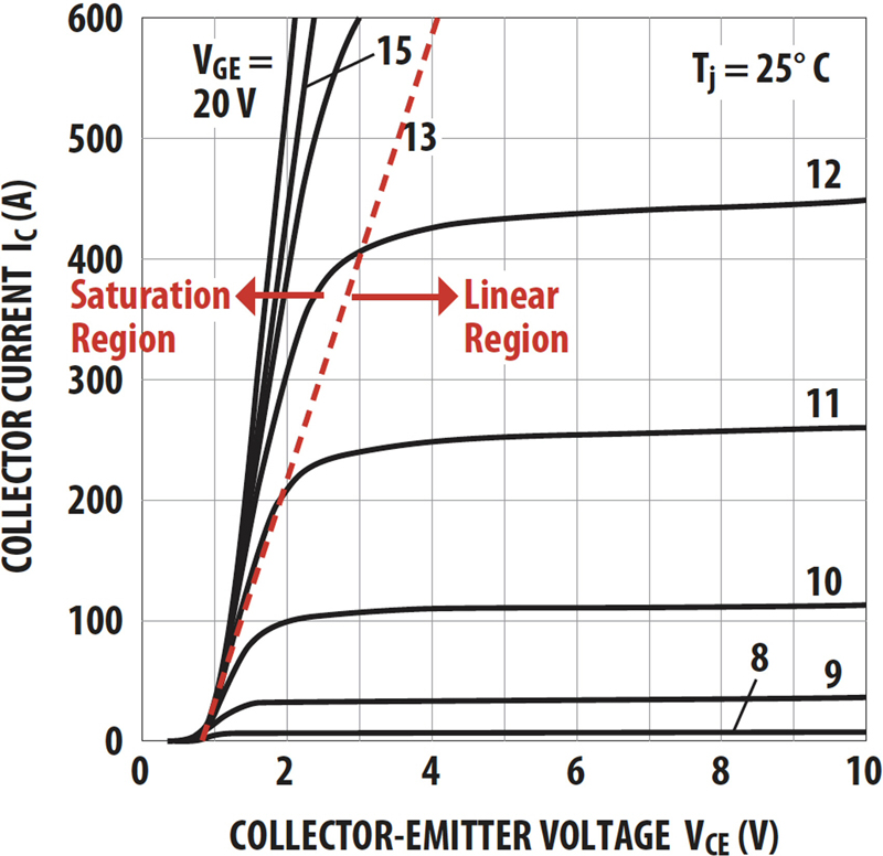
Inverter Fault Protection For high inverter reliability in the home-energy system, IGBT transistor drivers must incorporate circuits to prevent or mitigate common failure modes that can damage the IGBT. Normally, the IGBT is operating in the transistor's saturation region, which allows it to conduct high currents with a low VCE voltage drop across the transistor (Figure 2). To enter this state, the IGBT needs at least 12 V on its control gate. A home energy system can fail to meet that gate drive requirement in several ways An excessive load or a direct short on the inverter's AC mains would result in abnormal current through the IGBTs causing the voltage drop across the transistor to rise and quickly lead to device failure. Another way for the IGBT to leave its saturation region is for the gate-control voltage to drop below its minimum level. This drop can occur if there is a decline in the logic supply voltage due to deep battery discharge, if power generation has been insufficient to meet demand over a sustained period. As with the excessive current draw condition, the low gate voltage results in a rise in transistor voltage, VCE, and heating leading to device failure.
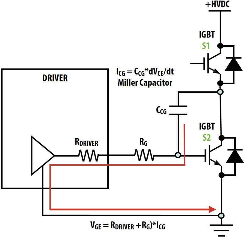
Failures also arise from the inevitable parasitic inductance and capacitance in switching circuits. Inductance causes voltage spikes if the IGBT shuts its output down too quickly, which can be large enough to damage the device. Energy stored in a the parasitic Miller capacitance at the IGBT's control gate can cause one switch of the pair to stay closed too long, resulting in a short circuit across the DC Link (Figure 3). Fortunately, protective circuits can prevent or mitigate these failure modes, and signal the system controller when a fault has occurred. An under-voltage lockout circuit, for instance, can ground the gate voltage, keeping the IGBT turned off in the event the supply voltage is too low to provide proper gate drive. Such a circuit should include hysteresis, however, to avoid oscillation when the supply voltage is at the lockout threshold. Another useful protective circuit is a desaturation detector. This circuit monitors the VCE voltage across the IGBT. If it rises above about 7 V the IGBT is in danger of damage from excessive heating. The detector circuit shuts down the IGBT gate driver during desaturation, eliminating the danger. Careful circuit design and board layout can reduce parasitic inductance in the inverter, reducing the magnitude of transient voltages when the IGBT switches off, but they cannot guarantee eliminating the danger. Designing the IGBT driver for a soft turn-off, however, ensures that the transient voltages never become dangerous. Board design cannot eliminate the Miller capacitance; it is inherent in the IGBT's structure. A clamping circuit, however, can eliminate its effect. An active Miller clamp can monitor the gate voltage when turning off the IGBT, stepping in to short the parasitic capacitance when the gate voltage drops below a threshold, guaranteeing shutdown timing. The protection against fault conditions that these circuits provide as well as the protection against short-circuits that isolation provides, are both essential for enhanced safety and reliability in home energy systems. Optocouplers provide the isolation necessary to ensure user safety, preventing component damage despite high voltages present in the DC Link. Protective circuits in the IGBT gate drivers help extend inverter lifetime, preventing the most common failure modes. Together, these functions can help AESs achieve the reliability and safety consumers demand of an operating energy system. www.avagotech.com


