Moore's law observes that the number of transistors in an integrated circuit doubles about every two years
When the power supply voltage is decreased, voltage fluctuations can become more dangerous, requiring a high-performance DC-DC converter in order to operate within safe parameters. DC-DC converters can help to address these requirements, and power inductors are crucial components that affect DC-DC converters’ performance thereby enabling speed increases in LSIs while significantly reducing power requirements.
Design engineers must understand six key principles that help them to use and select power inductors in a way that is consistent with the intended application and characteristics of DC-DC converters. These include:
· How power inductors affect DC-DC converter performance
· Power inductor characteristics
· Changing conditions of loss
· Inductance values
· Leakage flux and acoustic noise
· DC-DC converters and power inductors characteristics
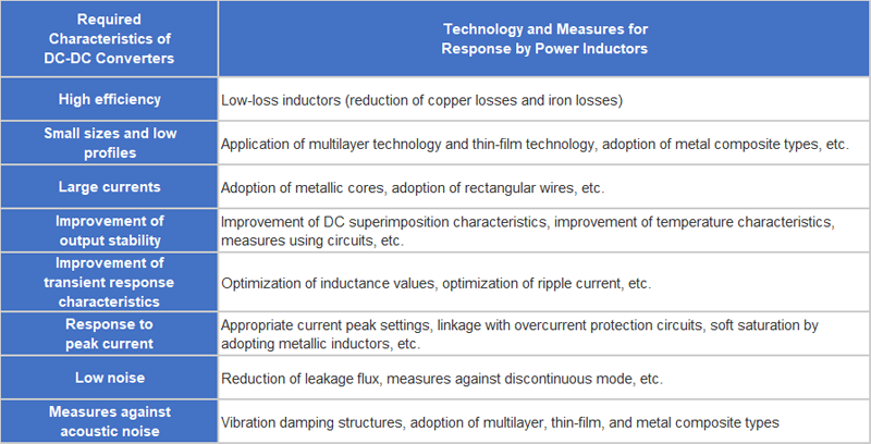
The following table shows the required characteristics of DC-DC converters and the related characteristics of power inductors which will be discussed in this article.
How power inductors affect DC-DC converter performance
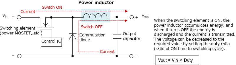
As vital components affecting DC-DC converter performance, power inductors are coils that can transmit direct current without fluctuations., Through a process called self-induction, power inductors create an electromotive force that obstructs and smooths out any fluctuations when current varies. With alternating current, this characteristic of inductors can also impede fluctuations in electrical transmission when it appears at higher frequencies.
As a result, inductors accumulate energy when electrical current is transmitted through an inductor that can be discharged if the current is interrupted or fluctuates down. Because of this characteristic, power inductors are most often used in power supply circuits and DC-DC converters, where they largely affect the performance of such devices.
Click image to enlarge
Figure 1: Basic Circuit of Step-down DC-DC Converter (Diode Rectification Type)
Power inductor characteristics
There are complex trade-offs that engineers need to understand regarding power inductors’ characteristics and the parameters of how they are used.
This difficulty originates from the many characteristics of power inductors and their applications. These may include factors such as temperature and current magnitude.
To illustrate some of these factors, the inductance property of power inductors causes a decrease of inductance as the current increases. This is known as the DC superimposition characteristic. Temperature increases that result from a rise of current, affect changes in inductor core magnetic permeability and saturation magnetic flux density. Noise characteristics is also affected by the magnetic shield structure. DC resistance can also change with the same inductance value depending on the thickness and number of windings. This may cause affect how heat is generated.
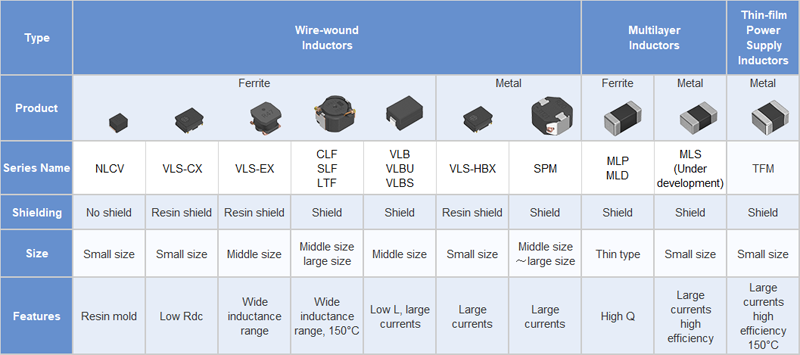
Power inductors are normally categorized as wire-wound, thin-film and multilayer inductors. This is based on their design and production differences. Manufacturers often utilize magnets, ferrite or other metallic magnets as power inductor cores. Ferrite cores exhibit high inductance and a high magnetic permeability value, whereas metallic magnetic cores exhibit exceptional saturation magnetic flux density. This makes them ideal for larger current applications.
In addition, power inductors work with two main types of ranted currents: allowed current for DC superimposition, and allowed current for temperature rise.
The inductance of the power inductor core will drop when the core becomes magnetically saturated.
The maximum recommended current that should eb transmitted without reaching magnetic saturation is the same as the allowed current for DC superimposition. The current that is defined by the heat generation of the electrical resistance in the inductor’s windings is the allowed current for temperature rise. The rated current for the inductor is should be equal or less that these two types of allowed currents. For example, there may be a drop of 40 percent from the initial inductance value and a rise of temperature of 40℃ due to self-heat generation.
Each of these parameters are co-dependent with each other and very complex, making each power inductor unique and uniquely suited for different applications. Consequently, the selection of the right inductor for each application is critical to it success.
In addition to the application in which they will be placed, the size, cost and efficiency of DC-DC conversion should be considered when selecting the most appropriate power inductors for any application.
Changing conditions of loss
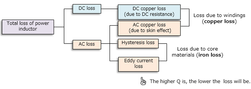
Loss will occur in every power inductor, and it is important to understand the types of loss that occurs. Losses can cause a rise in temperature. Copper loss is loss that transpires due to winding, whereas iron loss is loss that is due to core materials. Both can cause an increase in temperature. The circumstances that lead to loss are significantly affected by the various loads’ size and frequency on the power inductor.
Copper loss is often the result of the DC resistance of the windings (Rdc) and will increase proportionally to the square of the current. Copper loss that occurs from the AC is common in high-frequency areas. Often, as the AC frequency increases the effective resistance value will increase. This is often referred to as the skin effect. Also, the current flow may concentrate around the conductor surface.
Iron losses increase proportionally to the square of the frequency and are often manifest in eddy current loss and hysteresis loss. In high-frequency areas, the core loss caused by eddy current loss becomes larger than in low-frequency areas. Efficiency in the core may be improved by selecting an inductor whose core materials have low core loss in high-frequency areas.
Power inductor loss also changes based on the load size. Under moderate to heavy loads, copper loss is a dominant characteristic, while iron loss is dominant during light loads. The DC bias current is large when currents flowing through inductors are moderate to heavy because of DC resistance.
Alternatively, with a light load, DC bias current flow is reduced so that copper loss is minimal. However, since the constant-frequency switching operation is performed - even during standby status – iron loss becomes dominant and efficiency decreases.
To reduce iron losses, engineers may lower the driving magnetic flux density during use. However, DC resistance becomes larger, notwithstanding the power inductor has achieved a higher inductance value.
Click image to enlarge
Figure 2: Power Inductor Loss Factors
Inductance values
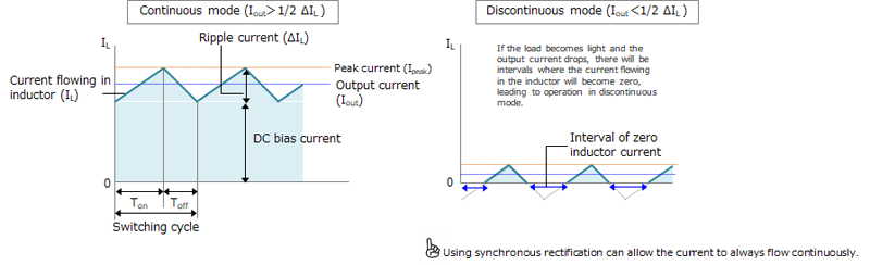
When selecting a power inductor, ripple current and other inductance values should be specified. For example, in selecting power inductors for step-down DC-DC converters, there will be a flow of ripple current with a waveform of continuous triangular waves during the ON/OFF operation of its switching elements. As a result, when they are used in discontinuous mode, it will affect the stability of the power supply.
This state known as continuous mode is where there is no interruption in the inductor current. This is achieved when the ripple current is superimposed on the DC bias current. However, in diode rectification DC-DC converters, there may be intervals where the inductor current becomes zero when there is a light load. The inductor current is interrupted intermittently. This state is known as discontinuous mode. Not only does this affect the stability of the power supply, but if the inductor operates in discontinuous mode, but acoustic noise will also occur and ringing will be generated in the pulsed voltage waveform as a result of switching. This will significantly add to noise generation.
Click image to enlarge
Figure 3: Continuous and Discontinuous Mode
The inductance value is related to the voltage applied to the inductor and the ripple current. Therefore DC-DC converters with diode rectification should be selected based on how they are designed to restrict ripple current and avoid the problems associated with discontinuous mode operation.
In doing so, engineers are forced to choose between the ripple current and the magnitudes of the inductance. If the ripple current needs to be reduced in the application, a large inductance will be required. This can increase the cost and size of the application as well as transient response characteristics. On the other hand, the ripple current will be larger if a power inductor is chosen on the basis of small inductance due to size or cost.
It is recommended that power inductors be specified so that the ripple current's inductance value is 20-30% of the rated current. In addition, the ripple voltage may be further reduced by using a low-ESR output smoothing capacitor.
If load increases suddenly, there will be a drop in the output voltage. Afterwards, the power inductor may allow an abnormally large peak current flow over a short period of time to charge the output capacitor and recover. However, if the allowed ripple current is small, the transient response characteristics needed to recover from the drop in voltage may not be possible.
The voltage drop can be suppressed by increasing the capacity of the smoothing capacitor. However, this will cause the recovery time to be longer. To assist with this, engineers may reduce the inductance value, thereby increasing ripple current. If the load response characteristics are deficient, the output voltage drops significantly; however, the inductance value is lowered and ripple current increased. The inductor current will become larger, speeding up recovery by reducing a drop in voltage. One caution in this method is that it is necessary to use a setting when lowering inductance value that considers the overall balance of the system.
Overcurrent protection circuits in power supply ICs and control circuits often have setting values and detection methods that vary widely. Overcurrent protection circuits must also be considered when selecting power inductors, especially when mounted externally.
When there is not enough latitude in the power inductor’s peak current, the overcurrent protection may activate and stop the output. As a rule of thumb, the peak value of the power inductor’s current flow should be set between 110-130% of the overcurrent setting value. In circumstances where excessive peak current transpires, a metallic inductor with a core that has gradual magnetic saturation characteristics is recommended to reduce abrupt inductance changes.

Click image to enlarge
Figure 4: DC Superimposition Characteristics for Ferrite and Metallic Cores
Leakage flux and acoustic noise
If the inductor’s switching frequency is 20kHz or lower, there could be vibrations from the core’s magnetostrictive effects and magnetic attraction will become audible. This is referred to as acoustic noise. Excessive fluctuations in load current may also cause this problem. The leakage flux from power inductors can affect their surroundings and also cause acoustic noise. Power inductors with magnetic shield structures help to reduce leakage flux and great care must be taken to reduce noise and leakage flux.
Switching from pulse width modulation mode to pulse frequency modulation mode can help to control the frequency and keep the pulse width constant under light-load conditions. This is one example of a method used to improve the efficiency of power inductors for DC-DC converters.
There are other methods addressing many of the trade-offs of power inductor characteristics, by working directly with the manufacturer or a with a qualified distributor. By doing so, design engineers can identify the most suitable power inductor for their application and improve the performance of DC-DC converters.
TDK offers a wide variety of power inductors with varying characteristics. For more information or specifications for your application, visit https://product.tdk.com/info/en/products/inductor/inductor/smd/index.html
Click image to enlarge