Author:
Wonsuk Choi, Fairchild Semiconductor
Date
09/26/2015
 PDF
PDF
Today’s industrial applications demand power supplies capable of delivering ever-higher levels of power density. That trend is escalating as regulatory agencies around the world impose new regulations to achieve higher efficiency, not only at full load, but also in standby mode and across the entire load spectrum. To meet these new requirements and maximize power density, power supply designers have turned to switch-mode power supplies operating at ever-higher switching frequencies.
Increases in switching frequency are limited by switching losses, however. To minimize switching loss, power supply designers have adapted soft switching techniques such as zero voltage switching (ZVS) or zero current switching (ZCS) for high switching frequency converters. Increasingly, designers are turning to resonant switching topologies as a solution for efficient switch mode power designs. In particular, LLC resonant half bridge converters are gaining attention.
Unlike conventional resonant converters, an LLC resonant converter gives designers advantages such as:
-Wide output regulation range with a narrow switching frequency range.
-Guaranteed ZVS even at no load.
-Utilization of all essential parasitic elements to achieve ZVS.
For these reasons, LLC resonant half bridge converters have become an essential topology for designers attempting to maximize efficiency and lower profile in industrial power supplies for telecom systems, servers, base stations, battery chargers, and solar inverters.
Solar inverters, where the photovoltaic (PV) needs to use renewable energy with maximum efficiency, are a perfect example for using the LLC resonant half bridge. Generally, for string level distributed MPPT (maximum power point tracking) structures, a transformer-less inverter achieves higher efficiency more easily, but achieving PV module grounding can be difficult; whereas inverters with transformers can achieve PV side grounding more easily, but they may suffer from lower efficiency. For string level distributed MPPT applications, a DC/DC step-up converter connected to a PV string can accomplish MPPT control. As a DC/DC converter, the high efficiency LLC resonant converter is used to interface the PV panel and produce DC link voltage.
Super-junction MOSEFTs
Power supply designers typically use super-junction MOSFETs to implement LLC resonant converters because of their extremely low RDS(ON) and EOSS. Unfortunately, the reverse recovery performance of a super-junction MOSFET’s body diode isn’t ideal for these applications. However, a new generation of 650V fast recovery super-junction MOSFETs, utilizing charge balanced technology, now offer a more rugged body diode, ultra low on-resistance, low stored energy in output capacitance, EOSS, higher threshold voltage (Vth) and fast switching speed.
Increases in efficiency and power density are enabled by the continuous development of novel resonant topologies and power devices which allow designers to move to higher switching frequencies at relatively low switching losses. That, in turn, leads to smaller converter dimensions. However, power MOSFET failures have been an issue in LLC resonant topologies.
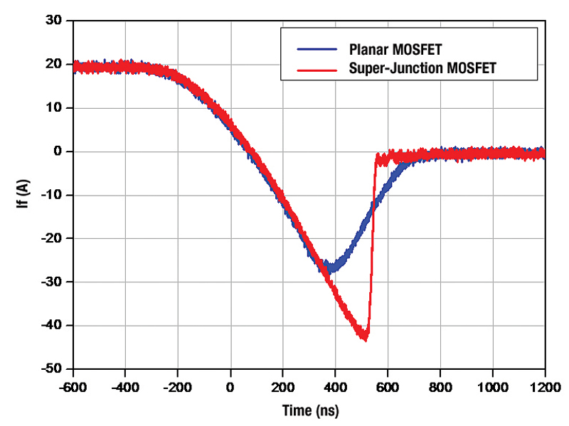
As shown in Figure 1, the reverse recovery of a planar MOSFET is relatively softer than that of a super-junction MOSFET. When all conditions are the same, “snappy” body diodes always produce higher voltage spikes and dv/dt, which can cause device failure. While the soft body diode of a planar MOSFET is suitable for resonant topologies, low RDS(ON) and EOSS are critical for maximizing system efficiency in an LLC resonant converter.
Click image to enlarge
Figure 1. Reverse recovery behavior comparison under Vdd=400V, di/dt=100A/us, Isd=20A
Furthermore, low QRR and robust body diode characteristics play a key role in reliability. Therefore, fast recovery super-junction MOSFETs are better suited than planar MOSFETs because they can effectively minimize the resonant energy required to achieve soft switching, and therefore improve system efficiency and reliability.
Low EOSS in LLC resonant topologies
Output capacitance plays an important role in LLC resonant converters. It determines how much inductance is required to achieve ZVS operations. ZVS is achieved by using the energy stored in the inductor, the leakage inductance or magnetizing inductance of the transformer, to discharge the output capacitance of the switches through resonant action. The inductance should be designed to prevent hard switching that causes additional power losses. The following equations (1) and (2) show ZVS requirements for an LLC resonant converter.
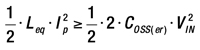
Equation 1
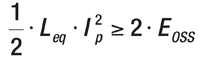
Equation 2
Where, COSS(er) is energy related output capacitance of the high side and low side MOSFETs at VIN, Leq is equivalent inductance.
Magnetizing current must be large enough to discharge the COSS of the MOSFET during dead time to ensure the ZVS turn-on as shown in equation (3) and (4). Low output capacitance can reduce the need for magnetizing current, less circulating energy, less turn-off loss and less dead time.
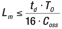
Equation 3
The peak magnetizing current (Ip) shows in equation (4)
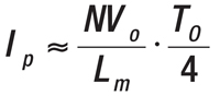
Equation 4
Where N is the transformer turns-ratio, VO is the output voltage, Lm is the magnetizing inductance, td is dead time and TO is the switching period. Turn-off current of the MOSFETs is determined by magnetizing inductance Lm. To achieve minimum conduction loss and turn-off loss, a large Lm is preferred.
Robust body diode in LLC resonant topologies
The LLC resonant converter requires a device with a rugged-characterized body diode, which experiences hard commutation during start-up or output short conditions. Body diode reverse recovery is the switching process of the body diode from an on state to a reverse blocking state.
When reverse voltage is applied across the body diode, the stored charge should be removed to go back to the blocking state. The removal of the stored charge occurs via two phenomena: the flow of a large reverse current and recombination. This reverse-recovery current flows through the body diode of the MOSFET because the channel is already closed.
This reverse recovery current and displacement current can trigger the parasitic BJT. Once the parasitic BJT turns on, a hot spot is formed and more current crowds occur. More current flows through the parasitic BJT due to its negative temperature coefficient. Finally, the device fails.
In short, body diode conduction should be minimized to lower peak reverse-recovery current. As the di/dt becomes larger, peak reverse-recovery current goes up as well. Therefore, a fast recovery MOSFET can prevent this failure thanks to its robust body diode performance.
One of the more important advances in the reduction of on-resistance in high voltage MOSFET technologies has been the development of charge-balance technology. Figure 2 compares the RDS(ON) of a SuperFET II MOSFET which uses an advanced charge balance technology with previous generation super-junction MOSFETs.
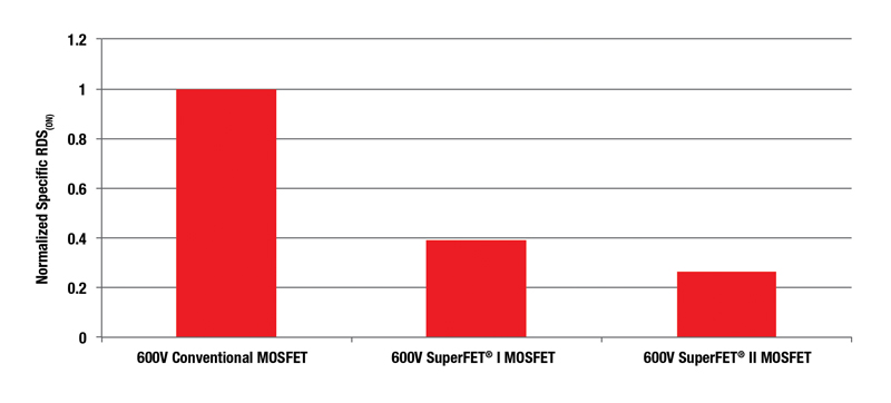
Click image to enlarge
Figure 2. Normalized On-resistance per Specific Area Comparisons
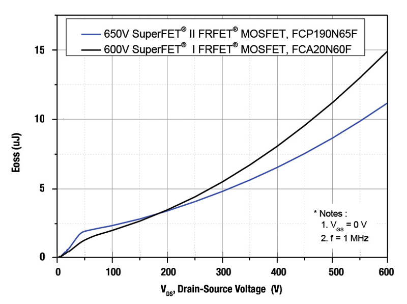
As shown in Figure 3, a SuperFET II FRFET MOSFET has approximately 23.3% less stored energy in output capacitance than a SuperFET I FRFET MOSFET at 400V across the MOSFET generated from a typical switching power supply bulk capacitor voltage. SuperFET II FRFET MOSFETs need less resonant energy to achieve soft switching without increasing the circulating energy in an LLC resonant converter compared to the previous generation.
Click image to enlarge
Figure 3. Comparisons of stored energy in output capacitance, EOSS
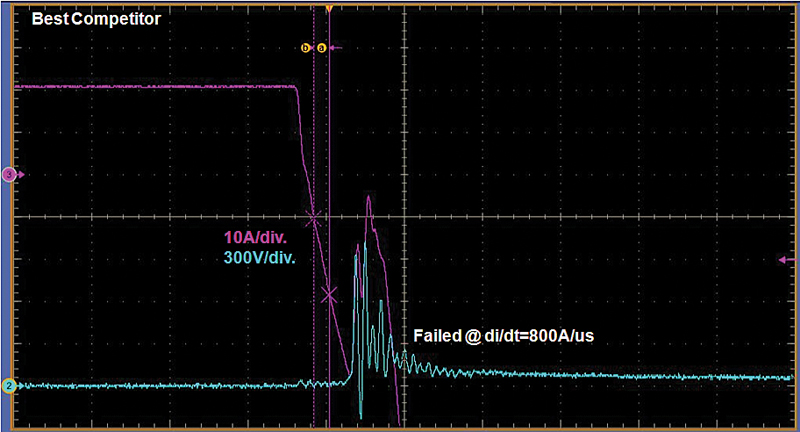
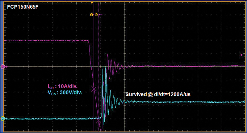
Figure 4 shows a fast recovery MOSFET’s failing waveforms during body diode reverse recovery. In this example, the failure occurs right after the current level reaches Irrm, peak reverse recovery current at 800A/us. As shown in Figure 5, SuperFET II FRFET MOSFET did not fail at even higher di/dt(1,200A/us) conditions.
Clcik image to enlarge
Figure 4. A typical fast recovery MOSFET’s failing waveforms during body diode reverse recovery
Click image to enlarge
Figure 5. MOSFET’s withstanding waveforms during body diode reverse recovery
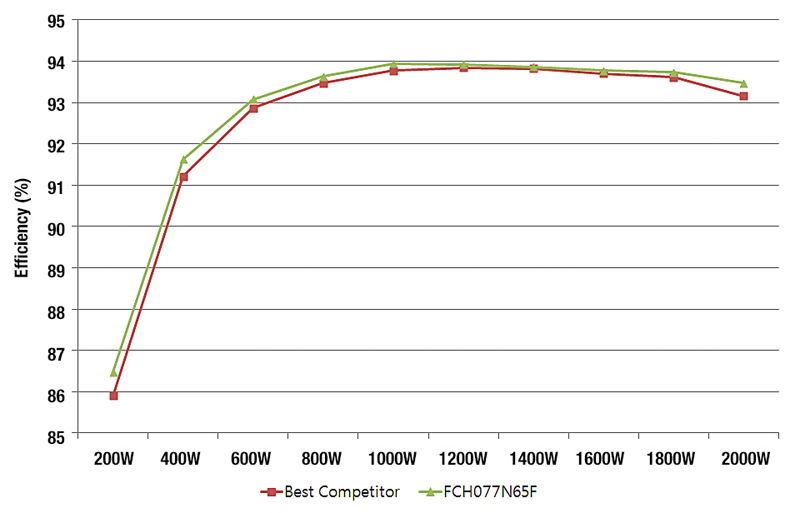
In the next chart we compare the efficiency of a SuperFET II FRFET MOSFET, FCH077N65F, 650V / 77mΩ and a comparable 650V / 80mΩ fast recovery SJ MOSFET in a 2kW telecom power supply. The summary of the efficiency measurements is shown in Figure 6. Efficiency increases about 0.58% and 0.31% compared to earlier generation MOSFETs at light load and heavy load conditions respectively. The major reason for the boost in efficiency is the reduced switch-off losses and output capacitive loss because of lower Qg and Eoss.
Click image to enlarge
Figure 6. Efficiency Comparison in 2kW Telecom Power Supply
Key capabilities for successful LLC resonant converters
Designers building energy efficient industrial solutions using LLC resonant converters need primary MOSFETs that can deliver the following key capabilities:
-Low RSP to reduce conduction loss and high power density.
-Low COSS and EOSS is to achieve soft switching with less resonant energy to reduce circulating energy.
-Small TRR, QRR, and less snappy body diode to avoid MOSFET failure by hard commutation during abnormal condition.
-Higher threshold voltage to reduce turn-off loss in ZVS operation.
A new generation of high performance MOSFETs promise to meet these requirements. Combining a faster and more rugged intrinsic body diode performance with fast switching, these MOSFETs achieve better reliability and efficiency in a wide range of applications including resonant converters.
By reducing gate charge and stored energy in output capacitance, they boost switching efficiency while reducing driving and output capacitive losses. This new level of performance allows designers to significantly increase system efficiency and reliability, particularly for in-phase shifted full-bridge converters or half-bridge LLC resonant converters under abnormal conditions.