Setting New Efficiency Benchmarks for Next Generation Motor Control Applications
Electric motors are continuing to evolve, as market requirements grow
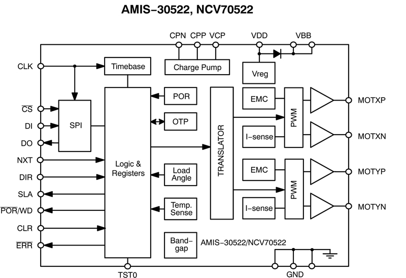
Figure 1: AMIS-30522 Functional Block Diagram
Electric motors are continuing to evolve, as market requirements grow for more compact, higher performance solutions which exhibit greater resilience to the often harsh environmental settings in which they find themselves. Though modern bi-polar stepper motors are capable of delivering both improved reliability and better accuracy than conventional motor offerings, OEMs and systems integrators still need to ensure they use all the tools and techniques available to them to maximize the effectiveness of these electro-mechanical devices. The following article discusses the merits of mapping system performance and how the employment of advanced adaptive control algorithms can raise efficiency levels and subsequently boost performance metrics. The use of adaptive control algorithms enables the full efficiency of the motor system to be gauged, taking into account the adverse conditions that the specific application may inflict upon it. This allows a much more comprehensive assessment of the system's ability to cope with its surroundings (whether these are industrial, automotive, or some other scenarios with exacting demands) and greater assurance of how well it will perform than would be possible by simply consulting the datasheets for the various constituent components it is made up of. In order to gain maximum efficiency, it is necessary for the boundary conditions of the complete motor system to be mapped. System variables such as motor speed, motor acceleration/deceleration, system temperature, mechanical degradation and supply voltage all need to be taken into consideration. The system architecture utilized will also have an effect on whether stipulated performance goals are reached. The possibility of resonance occurring is endemic to stepper motor systems. It can result from the motor running too close to its natural frequency. Ensuring that resonance does not take place is vital, otherwise the motor could lose steps or even stall. Motor Control Systems There are two basic types of motor control systems. These are: 1. Open Loop Systems - Here it will typically be necessary to stimulate the motor with the worst case current drive and velocity profile, as a result efficiency is not really a design goal. Mapping can be a long drawn out process, because the system has to be verified for all possible variables at which it will operate (to avoid possible risk of resonance) - supply voltages, temperatures, velocities, etc. Furthermore, pinpointing conditions where the stalling of the motor could arise can prove very difficult in an open loop system. 2. Closed loop systems - These consist of either a sensor-based arrangements, that use optical or magnetic sensing mechanisms, or sensor-less arrangements, which tend to detect the voltage generated by the motor windings moving through the motor's magnetic field. For sensor-based systems variation in the characteristics of the sensor must be considered when performance mapping is being undertaken. For sensor-less systems the data acquired is relative to the motor's physical motion. This simplifies system complexity and cost (as no external sensors are called for), although it does require a more in-depth knowledge of electro-mechanical theory. In sensor-less systems, through use of back electromotive force (EMF) it is possible to acquire detailed diagnostic data on the motor system. Between motor drive current pulses, the motor windings inherently produce a voltage as they move through the motor's magnetic field.
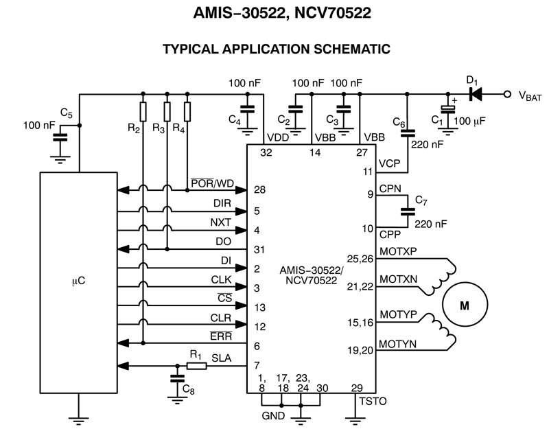
ON Semiconductor's AMIS-30522 micro-stepping controller IC (as shown in Figures 1 and 2) is designed specifically for use with bi-polar stepper motors serving the automotive, industrial, medical and marine sectors. As it provides a speed and load angle (SLA) output, stall detection algorithms can be created. The mapping of the SLA pin of an AMIS-30522 which has been incorporated into a Stegia stepper motor is described in Figure 3. The data used to compile this was collected during a frequency sweep of the NXT clock input. The frequency of the motor stimulus increases as it moves from left to right and the various regions of operation can be analyzed in detail. The capacity of the AMIS-30522 (and the other devices in this series) to measure the motor characteristics of a complete system gives OEM design teams much greater visibility. Rather than just being able to locate where motor resonance might occur, they can obtain knowledge of the complete mechanical system - how its performance changes with relation to the alteration of the many different variables involved and where the regions that may lead to operational issues lie. The motor system can continuously sample the voltage produced by the motor windings via the SLA pin and can rapidly respond should there be any issue that could have an unwanted effect on system performance. As back EMF has a direct relation to the rotors speed it can be employed to measure the external load on the output shaft and regulate the current being supplied to the motor. In addition, creation of an algorithm which is able to rapidly detect entry into a resonance region means the system can accelerate the motor out of this region until it is returned to a speed which is safe.
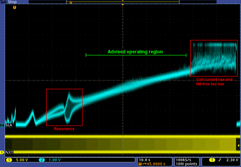
The red area found on the left of Figure 3 highlights a resonance in the system. This could be due to a number of different factors, such as the physical mounting of the motor, or the motor�s fundamental resonant frequency between steps. These are usually regions of commutation speed to be avoided and can be easily mapped through the back EMF approach. This can reduce the strain placed on the motor system and lower concerns about reliability. The red area on the right of Figure 3 highlights where the current drive is above the system's RLC time constant, leading to residual current flow within the motor windings. This gives the maximum speed limit that is recommended for the motor system. The recommended operating region for the motor is found between the two red areas. In addition, this mapping technique can be used to spot a stalled condition in which the motor does not commutate and, therefore, no back EMF is generated. Such conditions can easily be dealt with by the system controller through configuration of a minimum threshold during motor stimulus. Applying Mapping Data to Improving System Design After the mapping process has been completed and the optimal velocity profile has been identified, the SLA value that offers the best overall performance metrics can be chosen - this denotes the system's most efficient operating point. The variables listed earlier (such as motor acceleration, motor speed, etc) can be dynamically adjusted to ensure that issues that could impinge on system efficiency (like resonance) can be avoided. As motor systems continue to require ever higher precision and greater reliability, the need for diagnostic feedback is certain to grow. This means that highly integrated, feature-rich semiconductor solutions will be needed for supporting stepper motor devices. As sensor-less control loop systems can deliver feedback that is not of a binary nature, they can be used to draw detailed diagnostic information about the motor without additional system complexity needing to be added. This means that subtle changes in SLA output can be utilized for real-time compensation before step loss or stall situations are arrived at. www.onsemi.com www.stegia.se