Setting Up a Single Pair Ethernet System with Power Over Data Lines

Single-pair Ethernet with power delivery
In industrial applications, Single Pair Ethernet already promises significant simplification in the cabling of factories. If the connected devices are also supplied with power via the same two-wire cable, this is all the true, as a reference design from Würth Elektronik shows.
Single-pair Ethernet (SPE) is an emerging standard for Ethernet communication that uses only one pair of wires for data transmission, as opposed to traditional Ethernet, which typically uses up to four pairs of wires. This makes SPE suitable for applications where space and weight constraints exist, such as automotive, industrial and IoT (Internet of Things) devices.
Power over Ethernet (PoE) on the other hand is a technology that enables the transmission of electrical energy together with data via Ethernet cables. So, no separate power cables are required, which simplifies installation and reduces costs, especially for applications such as IP cameras, VoIP telephones and wireless access points. Power-over-Data-Lines (PoDL) extends the concept of PoE to Single-Pair-Ethernet by enabling power to be supplied via the single twisted pair cable used for data transmission in SPE systems. This allows devices connected via SPE to be powered via the same cable used for data transmission. In the literature, Single Pair with PoE is often also referred to as SPoE, which is used in the following explanations.
The reference design for single-pair Ethernet (SPE) with Power-over-Data-Lines (PoDL) from Würth Elektronik is a system that can transmit data between two points via a two-wire cable. The central device supplies the peripheral device with power via the same two-wires over which the data is simultaneously transmitted.
SPoE technology
SPoE differs from PoE in its definition and implementation. It includes:
· a unique power coupling technique used in a 2-wire circuit.
· simultaneous transmission of power and data via a symmetrical, twisted pair of wires.
Click image to enlarge
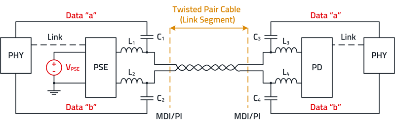
Figure 1: Basic circuit of an SPoE system
The data connections are realized via a single pair of wires, AC-coupled at each end to avoid ground loops. The PoE system transmits power simultaneously with the data. Figure 1showsthe basic circuit of the SPoE system. On the left-hand side of the circuit diagram is the Power Source Equipment (PSE) with the PHY (physical layer in the OSI model). On the right-hand side is the Powered Device (PD, load) and another PHY. The PHYs establish the data connection and the PSE supplies the PD with power. The data connection is capacitively decoupled (C1 - C4) from the power and the power supply is inductively decoupled (L1 - L4) from the data. The interface is referred to as a "Media Dependent Interface" or "Port Interface" (MDI/PI).
The integration of power delivery alongside data transmission demands a robust classification-based Power Delivery Protocol, designed to ensure compatibility between Power Sourcing Equipment (PSE) and Powered Devices (PD). The protocol employs a series of steps to establish compatibility and safety before delivering power, thus mitigating the risk of potential hazards such as short circuits or open circuits. The protocol initiates with the detection phase by the PSE, where it identifies the presence of connected PDs within the network. Following this, the PSE proceeds to classify the PD, requesting essential information such as class and type. Additionally, the protocol incorporates Cable Resistance Measurement (CRM), supported by the PD, to further assess the integrity of the connection. The protocol is defined in IEEE 802.3cg (SPoE, 2019), which is an extension of the 802.3bu Power over Data Lines (PoDL, 2016) standard. PoDL defines protocols for detection, classification, and power-up procedures, ensuring a standardized approach across various networking environments. Moreover, SPoE extends its capabilities to encompass long-reach protocols, exemplified by 10BASE-T1L, with the potential to span cable lengths of up to 1 kilometer. This opens doors to a multitude of applications, particularly in scenarios where traditional power delivery methods may be impractical or inefficient.
The electrical requirements for SPoE are defined in the following IEEE standards:
· IEEE 802.3cg (10BASE-T1): Bandwidth 0.1 to 20 MHz, range up to 1000 m.
· IEEE 802.3bw (100BASE-T1): Bandwidth 0.3 to 66 MHz, range up to 40 m.
· IEEE 802.3bp, (1000BASE-T1): Bandwidth 1 to 600 MHz, range up to 40 m.
The cables used for SPoE differ from the standard cables used for Ethernet.
SPoE requires cables that are defined in IEC 61156, i.e. "multicore and balanced pair/quad cables for digital communication". Standard CAT 6 or CAT 7 cables, even if they are shielded, are not suitable.
IEEE 802.3bu is a standard adopted by the IEEE in 2016 for powering devices over a single-pair Ethernet connection. The cables vary depending on the application, cables type A include solid wires for permanent installation, type B cables have wires with stranded conductors for flexible applications or vibrations.
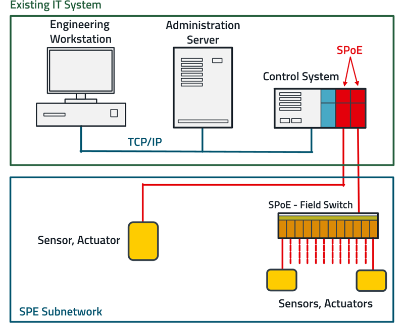
SPoE can be integrated into a mixed system with common industrial Ethernet protocols such as Ethernet/IP, Profinet and EtherCAT and can provide a simultaneous power supply for end devices. Figure 2 shows a typical setup.
Click image to enlarge
Figure 2: Adding SPoE devices to an existing IT system
The PSE tests the link before turning on the powerby using a 10 mA test current to check if the voltage drop is within a specified range. If the PD is found, the device class is determined by a so called “Serial Communication Classification Protocol” (SCCP). After having determined the PD-class the power is ramped up. Depending on the system, supply voltages can be 12 V, 24 V, 48 V and power classes range from 0.5 W to 50 W at a maximum current of 2 A. When not providing full power, the PSE continuously sources below 1 mA at 3.3 V (Sleep Mode).
SPoE division of functions
The hardware topology of the SPoE reference design RD041 consists of two boards, the PSE circuit and the PD circuit. The interfaces with primary transient protection, common mode chokes, transformers and secondary transient protection to the PHY are the same for the PSE and the PD.
Power and data are coupled together at the interface via a power coupling network.
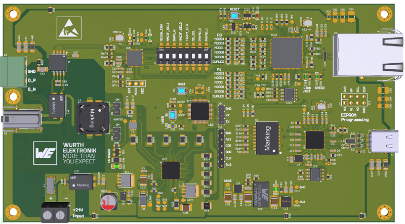
Click image to enlarge
Figure 3: Top side of the PSE board, the SPE interface is located on the left, the connection can be made either via a 3-pin plug-in terminal or an SPE connector
Conventional IEEE 802.3 multipair Ethernet (including PoE) requires galvanic isolation from the chassis ground. According to IEEE 802.3bu (PoDL) and IEEE 802.3cg (SPoE) standards, PSE/PDs must provide at least 1 MΩ (@ 5 V ± 20%) isolation between all accessible external conductors and the interface (MDI). Depending on the application, the equipment must comply with relevant standards such as IEC 61010-1 (Safety regulations for electrical measuring, control, and laboratory equipment) or IEC 62368-1 (Safety requirements for equipment for audio/video, information, and communication technology). Devices with no electrically conducting pins, except the twisted-pair Ethernet MDI, can meet isolation requirements by using a nonconductive chassis enclosure.
For SPoE applications requiring galvanic isolation from the chassis, an isolated power supply must be utilized. Relevant safety standard requirements including clearance and creepage distances, as well as protective distances, must be adhered to.
The SPE transmission path operates at a data rate of 10 Mbit/s with an amplitude of approx. 2.5 VPP, the operating voltage on the two-wire line is 20 to 24 VDC.
The PSE and PD implementation are described in detail in the paper of the reference design RD041.
Figure 3 shows the top side of the WE PSE board, Figure 4the top side of the WE-PD board.
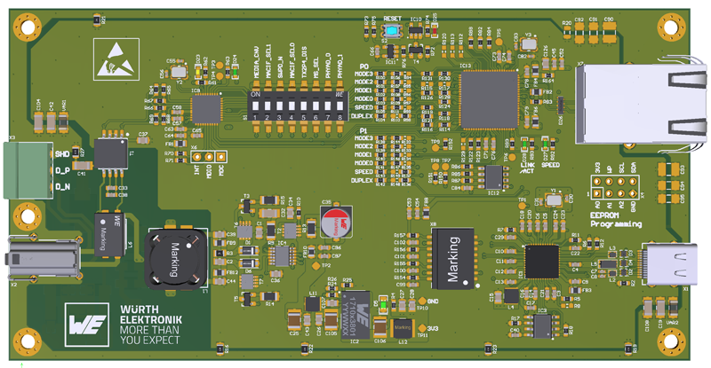
Click image to enlarge
Figure 4: Top side of the PD board, on the left is the SPE interface, the connection is made either via a 3-pin terminal or an SPE connector
The reference design presented has not been tested in 1000 m range mode, so only operation with cable lengths of up to 100 m is currently recommended.