SiC FETs in Traction Applications Maximize Efficiency
Wide bandgap switches are set to take over from IGBTs in traction inverter applications for an increase in efficiency with the consequent energy savings and extra range
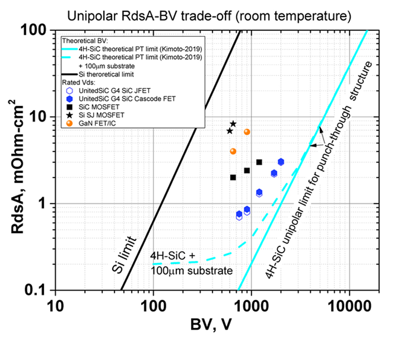
Figure 1: Figure of merit RDS∙A compared for technologies at increasing voltage rating
A traction inverter is an application that is peculiarly unique; power conversion electronics is generally pushing to ever-higher switching frequencies for higher power density, but a motor drive typically seen in an EV is still operating around 20kHz. The reason is that the magnetic element is the motor, which is sized for torque and power, and there is little benefit from switching it at high frequency. This means that rugged, low-cost, but slow-switching IGBTs can be used.
Improving on IGBTs
Although IGBT-based inverters can reach creditable semiconductor efficiency levels of 98+%, there is continuing pressure to improve further, as this enables either a smaller and lighter battery pack or longer range. SiC MOSFETs are an obvious alternative to IBGTs and are increasingly recognized as competitive in EV motor drives.
There is another choice however, UnitedSiC FETs, a cascode combination of a SiC JFET and a silicon MOSFET. These provide significantly lower on-resistance with an easy gate drive and better performance than SiC MOSFETs in other respects. A useful comparative measure is RDS∙A, the product of on-resistance and chip area for a particular voltage class. Figure 1 shows how the different technologies currently perform.
The theoretical limit for Si is shown to be broken by the application of super-junction technology and the limit for SiC may well be exceeded in the future by the same techniques. As of today however, the UnitedSiC ‘Generation 4’ FETs give a significant advantage in RDS∙A over SiC MOSFETs and GaN HEMT cells. In addition to extremely low on-resistance, RDS∙A advantage of UnitedSiC FETs includes low switching losses due to low device capacitances.
In traction applications, ruggedness is an important factor, and UnitedSiC FETs excel here as well, with a defined high-energy avalanche and short-circuit withstand rating. Furthermore, they have no MOS gate on SiC, so no parameter drift with voltage, temperature, or high reverse current. A final bonus is the fast, low-drop body diode inherent in the UnitedSiC FET, eliminating the need for an external anti-parallel diode, which is required when IGBTs are used in motor drives.
Practical performance results
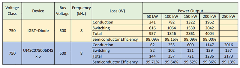
The better performance of UnitedSiC FETs compared with IGBTs can be seen from real-world results shown in Table 1 for a traction inverter with a 500 VDC bus. An IGBT plus diode module is compared with 6 parallel TO-247 packaged UnitedSiC FETs for each switch position in a two-level voltage-source inverter. At 200 kW load, the UnitedSiC FET solution reduces losses by 3.1x, or from 4 kW down to 1.3 kW. The percentage improvement is more at light loads, where a vehicle often operates, with a 5-6x loss reduction. This is because the UnitedSiC FETs have no ‘knee’ voltage, and the gate drive power is a fraction of the IGBT solution.
Click image to enlarge
Table 1: UnitedSiC FETs yield much lower losses than IGBTs in a traction inverter
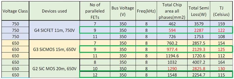
When comparing UnitedSiC FETs with SiC MOSFETs, the first notable point is that UnitedSiC Gen4 FETs are available with 750 V rating, while SiC MOSFETs are more common at 650V rating. This supports increased battery voltages and/or design margin. Table 2 shows results from another inverter running at 200 kW load and with a bus voltage of 350 VDC, comparing 11 mΩ UnitedSiC Gen4 FETs with Gen2 and Gen3 SiC MOSFETs. Devices have been paralleled to give approximately the same loss and junction temperatures. What stands out is that UnitedSiC FETs require only 50% to 60% of the total chip area of G2 or Gen3 SiC MOSFETs respectively. Generalizing this, UnitedSiC FETs provide lower total losses than SiC MOSFETs for a given chip area. This puts the UnitedSiC FETs on an improved cost versus efficiency tradeoff curve.
Click image to enlarge
Table 2: UnitedSiC FETs compared with SiC MOSFETs
UnitedSiC JFETs have a place too
While UnitedSiC FETs have been described, at the heart of the device is a SiC JFET, a very simple vertical structure with minimum channel resistance. The UnitedSiC JFET is normally-on, which is why the cascode configuration is offered, to make the composite FET normally-off. However, there is an advantage to using SiC JFETS as the low-side (or high-side) switches in each leg of an induction machine drive inverter.
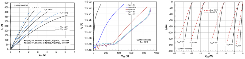
Let’s first take a step back and review the basic characteristics of a UnitedSiC 5 mΩ, 750 V SiC JFET. Figure 2 (left) shows forward characteristics, with the channel conducting at VGS = 0 and 2 V and various junction temperatures. Note that a slight positive gate voltage, +2 V in this case, gives a useful reduction in RDS(on) of about 10% compared with VGS = 0 V. Figure 2 (middle) shows the JFET in its blocking state with VGS = -10 V, adequate for negligible leakage current. Figure 2 (right) is an indication of third-quadrant operation where voltage drop with reverse current depends on the off-state gate voltage, similar to GaN HEMT cells. For this reason, efficient third quadrant operation requires the JFET to be switched on after minimal deadtime.
Click image to enlarge
Figure 2: JFET characteristics (UnitedSiC UJ4N075005K3S)
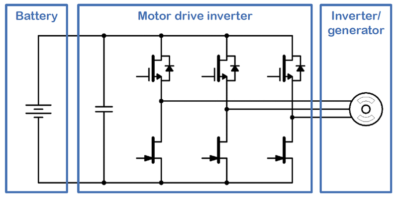
Within these constraints, JFETs can be utilized in low side switch positions as in Figure 3 to give some benefits. The SiC JFET has about 9% lower RDS(on) than a cascode with the same JFET inside. If control power is lost, all low side switches turn on. This shorts the motor windings to a fail-safe condition for an induction machine, with no uncontrolled torque and power to the battery pack. Under such a fault condition, the normally-off high-side switches prevent damaging shoot-through.
Click image to enlarge
Figure 3: SiC JFETs in the low-side switch positions of an inverter
As an added benefit, when the JFET is driven to the on-state at a fixed positive bias current of say 10 mA, the gate-source PN junction voltage varies linearly with junction temperature. This can be used for direct, fast-acting JFET temperature monitoring and as a long-term motor drive “health” indication.
UnitedSiC FETs and JFETs are a winning combination
UnitedSiC FETs are improve efficiency in traction inverters. Additionally, use of UnitedSiC JFETs for the low-side switches further reduces losses and adds fail-safe functionality for induction machines. Devices are available from UnitedSiC, now Qorvo, with a range of on-resistance options allowing designers to choose the best cost/benefit combination. The online FET-Jet Calculator allows rapid selection of an optimum device.