SiC JFETs are the Future of Solid-State Circuit Breakers
SSCBs offer more than circuit protection - they can also protect people, be used for remote monitoring, and can be monitored and set up remotely
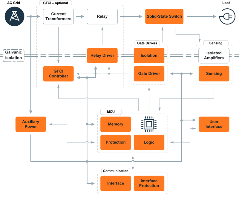
Figure 1: Block diagram of a solid-state circuit breaker
A circuit breaker is a device used to protect electrical circuits from damage caused by overcurrent, overload, and short circuits. An electromechanical breaker (EMB), the de facto standard, consists of two separate triggers: bimetal, which is slow and tripped by overcurrent, and electromagnetic, which is fast and activated by short circuit. EMBs have a defined trip current, usually fixed, with instantaneous (electromagnetic) and delayed (thermal/bimetal) trip characteristics to handle short circuits and overloads safely.
While an EMB is simple and effective, it has some disadvantages. One of them is speed. EMBs operate in the millisecond range, during which a fault current can still cause damage or even harm the user. Another drawback is arcing: when contacts separate, an arc forms and energy must be safely dissipated, producing thermal and mechanical stress on the breaker.
Replacing mechanical contacts with semiconductor switches eliminates arcing, as current interruption occurs electronically before any physical contact separation. Semiconductor switches can turn off in microseconds, significantly reducing peak short-circuit currents. Furthermore, unlike mechanical components, they are built for frequent operation and do not degrade over time. These semiconductor switch-utilizing devices are known as solid-state circuit breakers (SSCBs) and are generally utilized for the protection of both DC and AC circuits.
Understanding Solid-State Circuit Breakers
The advantages of SSCBs are clear: semiconductors can switch more quickly and reliably, are more durable (no wear and tear), and offer more precise control. In the case of failure, the faster disconnect is better, and a semiconductor switch is more than 1000 times faster than mechanical ones. What’s more, the already required control electronics allow the breakers to include other new features, such as current and voltage monitoring, change of current limit, and other safety add-ons like residual current devices.
At the heart of the SSCB is a semiconductor switch, which replaces traditional electromechanical relays. An SSCB operates by monitoring the current and temperature of a circuit and feeding that data to a microcontroller unit (MCU). The MCU continuously monitors current and temperature to detect faults and trigger protective shutdowns within microseconds. In the event of a trip, the MCU tells the gate driver to “turn off” the switch. All of this happens in a fraction of the time that it takes an EMB.
For safety, an optional mechanical relay may provide physical isolation after semiconductor turn-off, eliminating arcing and handling only small leakage currents. The relay operates without an arc, as it is turned off after the semiconductor, and therefore does not need to be rated for short currents. It disconnects the leakage current of the semiconductor, which is in the hundreds of µA. Moreover, this relay completely disconnects the device because, unlike a mechanical circuit breaker, the SSCB is connected to both the phase and neutral lines.
Classification of Semiconductor Switches
The idea of replacing mechanical switches with semiconductor switches is not new, but for a long time, the limiting factor was the state of semiconductor innovation. Nowadays, with advancements in the wide band-gap technology, solid-state devices suitable for low-voltage residential and commercial networks have begun to appear.
One limiting factor to mass-market adoption of an SSCB is the on-resistance. While modern semiconductor switches and particularly MOSFETs have low on-resistance, it is still much higher than that of mechanical contacts.
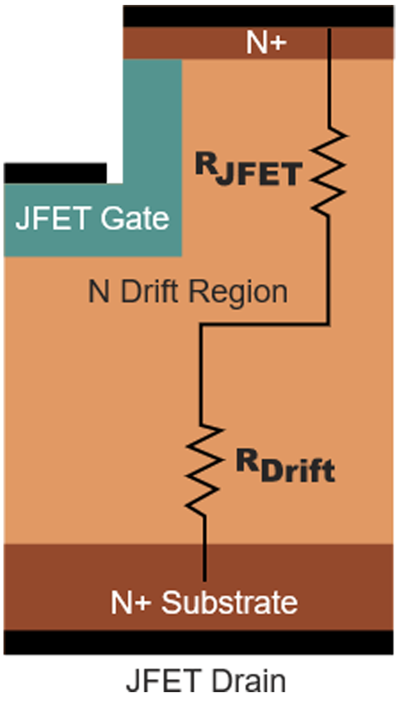
Over the last few years, the Silicon Carbide (SiC) junction field-effect transistor (JFET) has emerged as the leading technology to drive SSCB forward. It takes advantage of SiC material properties like high thermal conductivity, higher voltage class, and lower losses, and combines with the pros of the JFET structure. JFET has the lowest RDS(ON) per area on the market and is voltage-controlled like a MOSFET. This is because the device employs a junction-gate structure, unlike the oxide-gate in a MOSFET, providing a direct drain–source current path with minimal charge trapping and negligible surface leakage.
Click image to enlarge
Figure 2: JFET structure
The drawback of this low resistance is the JFET’s normally-on characteristic, meaning that if the gate is left floating or there is no gate voltage, the device is fully on. This is generally a disadvantage in most applications and control schemes, as the preferred state in the case of failure is the off state.
A normally-off device can be created by serially connecting the JFET with a normally-off Si MOSFET, which functions as the enable for the SiC JFET, preserving the benefits of the JFET structure. This configuration is known as cascode, and the device is very versatile and can be used in a variety of applications. The cascode JFET (CJFET) has flexible gate drive and low switching losses, but only has access to the gate of the low-voltage Si MOSFET, and the device switches too fast for the SSCB.
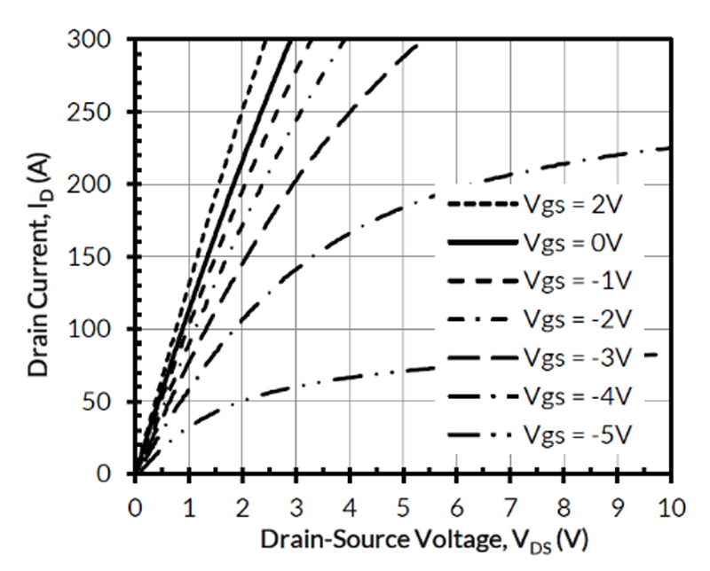
Another available configuration is a combo JFET, which also contains both LV MOSFET and JFET in one package. The difference is that it allows separate access to both MOSFET and JFET gates and thus permits more control of switching dV/dt. This configuration also allows further reduction of RDS(ON) by overdriving the JFET gate. Although the JFET is open even at 0 V gate voltage, applying a positive gate voltage enhances the channel conductivity, reducing RDS(ON). This can be seen in Figure 3.
Click image to enlarge
Figure 3: Combo JFET output characteristics
As stated above, power dissipation remains the biggest limiting factor for the wider adoption of SSCBs. If they are to be used in residential environments, they have to be backward compatible with currently used devices, in which there is not a lot of space for cooling. The mechanical circuit breaker has very low losses due to the very low resistance of the current path. The culprit for the power loss in the SSCBs is not only the on-resistance of the FET, but also the power loss in the control electronics, which is more or less constant and independent of the load.
When the device is used for AC blocking, it requires a back-to-back configuration, since a JFET can only block voltage from source to drain. This further complicates the requirements as it effectively doubles the channel resistance. Therefore, to reduce the total RDS(ON), a parallel configuration is used. This further highlights the combo JFET as the preferred switch, as it allows and simplifies parallel operation.
When the fault occurs in the SSCB, the current starts to rise and flow through the semiconductor to the load until it is turned off. During turn-off, the voltage rises sharply, and the voltage clamping circuit is triggered by overvoltage and protects the MOSFETs from avalanche. Fault current continues to flow to the load through the clamping circuit until fully turned off. Circuit energy stored in inductances, which includes wires and an inductive load, is dumped in the clamping circuit. With faster detection time, lower current rise, and less energy needing to be dumped, this in turn translates to a smaller clamping circuit.
For voltage clamping, the two most used devices are metal-oxide varistors (MOV) and transient-voltage-suppression (TVS) diodes. MOVs are bi-directional, cheaper, and have higher power density, but tend to have shorter lifetime and are worse at voltage regulation due to capacitance between their two electrodes.
On the other hand, TVS diodes can be both uni- and bi-directional and have lower capacitance but have higher space requirements and are pricier for high-current versions.
Conclusion
SSCBs elevate the traditional devices with more functionality at the cost of higher expenses. They offer more than circuit protection; they can also protect people, can be used for remote monitoring, and can be monitored and set up remotely. Due to them having much higher repeatability, they are much more suitable in environments expecting a higher tripping rate. onsemi offers SiC JFET and SiC Combo JFETs with very low RDS(ON). Even though SSCBs are penetrating the market, mass adoption has not arrived, mainly due to the challenges with power dissipation at higher voltages and currents. Devices like SiC JFETs and combo JFETs will help drive adoption of the advantageous solid-state protection solutions.


