Silicon Carbide E-Fuse Demonstrator Offers Designers Solution for Circuit Protection in Electric Vehicles
Electric vehicles with 400V battery systems were introduced over a decade ago and now we are seeing the industry migrate toward 800V systems primarily to support DC fast charging
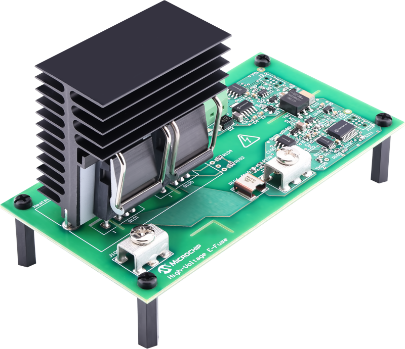
Figure 1: Microchip's Auxiliary E-Fuse Technology Demonstrator
With the increased voltage and lessons learned from 400V systems, designers are now focused on enhancing the performance of high-voltage protection circuits along with improving reliability. The incumbent solution using a fuse, contactor or relay is being reevaluated for faster-reacting, more robust and reliable solutions such as pyrofuse and electronic fuse, or E-Fuse. A leading solution is an E-Fuse based on silicon carbide (SiC) technology. SiC offers a high operating voltage, high operating temperature, low on-state resistance, low off-state leakage current and durability against over-voltage transients. The E-Fuse's solid-state design eliminates reliability issues related to arcing, mechanical wear-out, contact bounce and tack welds. The economizer hardware for driving contactor coils is no longer needed. E-Fuse improves system-level performance with its configurability, controlled turn-on and turn-off, on-board diagnostics and durability to high-voltage transients.
Resettable Design Eliminates Need for Service
With an all SiC-based design, E-Fuse has an unparalleled response time to short-circuits, reacting several hundred times faster than even a pyrofuse. This makes E-Fuse a natural complement to a pyrofuse-based protection solution. While a pyrofuse offers robust, reliable circuit protection, it is not resettable. It’s a one-time use device, like the pyro in an airbag.
A pyrofuse is implemented as a failsafe measure to deenergize the system in severe situations. Once detonated, it requires replacement. Replacing a component in a high-voltage system is not as easy as it is on a 12V system. With system voltages of 400V or 800V, well above the 60V limit that the automotive industry generally deems as safe, repairs can only safely be done by qualified service technicians. Fortunately, with a configurable trip profile, an E-Fuse as a system-level companion solution can be more sensitive to over-currents than a pyrofuse, ensuring it trips first, preventing the triggering of the pyrofuse. An advantage of E-Fuse over today’s solutions is that it’s resettable, saving the EV owner the time, expenses and headaches associated with taking a vehicle in for service.
Robust DC Circuit Protection
Circuit protection in high-voltage DC systems poses a unique challenge. Unlike AC systems, where the zero-cross aids in the extinguishing of an arc, DC systems do not have such a zero-cross. To combat this, high-voltage EV relays and contactors include additional sophisticated features to safely quench arcs. However, arcs still erode the contacts, and result in reliability issues such as high contact resistance or tack welds.
On the other hand, E-Fuse safely disconnects DC circuits without generating an arc. The same type of inductive energy responsible for the arcing in a relay-based solution is present in an E-Fuse protected circuit, so an E-Fuse solution will need to absorb that energy when interrupting a current.
The main difference is an E-Fuse has a fast response time, reducing the peak current to orders of magnitude lower than a traditional solution. As the inductive energy is proportional to the square of the current, a decrease in the peak short-circuit current results in a significant decrease in let-through energy. It also leads to less stress on the wiring and a potential downstream faulted load.
E-Fuse Demonstrator with Configurable Trip Profile
Microchip’s auxiliary E-Fuse technology demonstrator shown in Figure 1 is available for designers developing automotive high-voltage E-Fuse or solid-state relays. The six hardware variants provide 400V and 800V options and current ratings of 10A, 20A, and 30A, allow evaluation of single or parallel SiC MOSFETs of RDS(on) ratings from 15 mΩ to 40 mΩ.
The E-Fuse control and protection circuits are powered by the 12V system. Equipped with a LIN communication interface, it supports options of connecting directly to the 12V battery, while waking up from sleep mode through LIN activity, or from a control module’s switched-battery output.
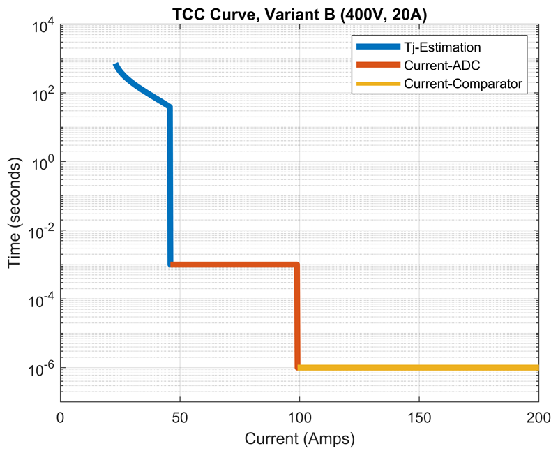
The E-Fuse includes three over-current detection methods spanning the range of a slight over-current to a very high short-circuit current, as illustrated in the time-current characteristic (TCC) curve in Figure 2. The TCC curve defines the E-Fuse’s fuse-like behavior with a slow response time to low over-currents and a fast response to high over-currents.
It can be easily adjusted to protect wiring and loads. The three detection methods are easily configurable through software or over the LIN interface. The leftmost detection method in blue characterizes the trip behavior using a junction temperature estimation algorithm. The algorithm uses the current measurement, ambient temperature measurement, SiC MOSFET’s RDS(on), and the thermal design characteristics to estimate the SiC MOSFET’s junction temperature.
The response time varies with the magnitude of the over-current. The middle line segment represents the detection method using the current measurement alone with a fixed response time. The rightmost line segment represents a hardware-based, though software-configurable, detection method. This leverages the PIC® MCU Core Independent Peripherals (CIPs), specifically a comparator, fixed voltage reference, digital-to-analog converter and configurable logic cells that are configured as SR latches. This enables fast signal propagation to under a few hundred nanoseconds, allowing immediate detection of a short-circuit and protection of the high voltage system.
Click image to enlarge
Figure 2: Time-Current Characteristic Curve for 400V, 20A E-Fuse variant
In addition to the fuse-like behavior, an E-Fuse can take on the function of an electromechanical relay. Just as a relay coil and its high voltage contacts are galvanically isolated, a high voltage E-Fuse also includes an isolation barrier between the control signals and high voltage terminals. Similar to a relay, an E-Fuse has the flexibility to connect in the system as a high side output feeding high-voltage battery positive to a load, or as a low-side output providing a path for the load to the high-voltage battery negative return as illustrated in Figure 3.

Click image to enlarge
Figure 3: E-Fuse System-Level Configurations
High-Voltage Short-Circuit Performance
To truly appreciate the difference in response time of an E-Fuse compared to a conventional automotive high-voltage fuse, each was subjected to a short-circuit under similar test conditions of 450V and approximately 3 µH of line inductance. The resulting waveforms are shown in Figure 4. The black waveform is of current flowing through the high-voltage fuse under test. Within 30 µs, the current reaches 3800A, which is the limit of the measurement equipment, and blows the high-voltage fuse 50 µs later. Based on the test parameters, the peak current is estimated to have exceeded 6000A. However, with an E-Fuse, as shown in the blue waveform, the current reaches only 128A before tripping. This is a significant reduction in let-through current, minimizing the stress on the wiring and downstream loads.
It gives system designers the option of optimizing the wiring for weight and cost. In some cases, the E-Fuse’s low let-through current will be the difference between a tow-condition, where a fault causing a high current stress results in permanent damage to hardware, and a recoverable fault that allows the system to automatically reset and the driver to continue operating the vehicle.

Click image to enlarge
Figure 4: Current waveforms for E-Fuse vs high voltage fuse
Beyond the electric vehicle itself, the support infrastructure, such as DC fast charging stations or microgrids supplying the charging stations, also stand to benefit from E-Fuse. The advantages an E-Fuse offers are not limited to automotive applications.
Applications using fuses and contactors benefit from some of the topics discussed as well as other advantages, including on-board current sensing, which enables further system-level integration and optimization. Off-board applications utilize a common-source, anti-series SiC MOSFET configuration and may require a higher current capability than the demonstrator offers. Fortunately, the design easily scales and may be adapted for use with SiC power modules available in a common-source configuration.
As we see the increasing focus on performance, safety and reliability, E-Fuse as a circuit protection solution will continue growing as the preferred method just as we’ve seen the shift in the 12V system from fuses and relays to protected solid-state drivers and more recently to low-voltage E-Fuses.

.jpeg)