Simple and Rapid Development of Brushless Motors
Advanced algorithms and easy-to-use hardware merge sophistication and simplicity
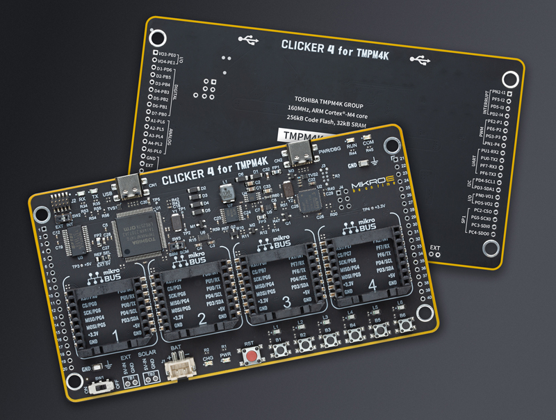
Figure 1: The Clicker 4 evaluation board for TMPM4K
Electrical motors in general are becoming more prevalent and have advanced significantly, especially regarding magnetics and design. This, along with size reduction and technology advances, have resulted in enhanced efficiency, faster speeds, reduced audible noise, and improved dynamic response.
Especially the control of BLDC motors can be a challenge requiring complex waveforms and sophisticated microcontrollers along with a lot of ‘know how’. Fortunately, there is a variety of solutions available including multiple development platforms and evaluation tools to simplify the evaluation and prototyping process and remove risk from the design process.
The challenges of driving BLDC motors
BLDC motor control requires the DC supply to be converted to a 3-phase signal. Depending upon the drive scheme selected, a position sensor may also be needed. Rotational speed of the motor is defined by the voltage and electrical frequency of the drive waveform, while the motor torque is proportional to the current. Typically, the PWM frequency is in tens of kilohertz so that it is not audible to humans, but not so high that efficiency is impacted.
The various methods of driving a BLDC relate to waveform shape. The square wave drive is the simplest method, but will induce some ripple, causing vibration and noise - especially at low speeds. The trapezoidal drive method is a better solution despite some disadvantages.
A sine-wave drive (‘sinusoidal commutation’) will eliminate the ripple, but this introduces complexity, needing a microcontroller for sine wave generation. It also requires higher precision in the position sensing.
Vector or Field-Oriented Control (FOC) is now very popular for its smooth operation across the entire speed range, rapid acceleration/deceleration and availability of 100% torque at zero speed. FOC can use position sensors but, equally, sensorless techniques are available.
FOC operation requires constantly performing complex mathematical calculations meaning that even simple FOC controllers require a pulse width modulator (PWM), software-based PI control, ADCs and a vector-capable processor.
Getting the BLDC motor moving quickly
As BLDC motors become more widely used, so the availability of expandable evaluation board concepts to simplify the integration of sensors, memories, and input controls has also expanded. One of the leading companies in this area is MikroElektronika (MIKROE), a Serbian manufacturer of embedded system software and tools. Based upon their well-established mikroBUS interface, MIKROE’s ‘Clicker 4 concept’ is aimed at providing low-cost and versatile BLDC motor control.
The Clicker 4 for TMPM4K is based around Toshiba’s TMPM4KNFYAFG microcontroller (MCU) that features a 32-bit ArmCortex-M4 core. The dedicated MCU includes four specialised peripherals that provide almost “set and forget” support for sensor-based and sensorless vector motor control.
The Advanced Vector Engine Plus (A-VE+) is a vector control accelerator that can deliver axis and coordinate transformation, perform space vector modulation, and provide hardware proportional-integral (PI) controllers. Once set-up the A-VE+ will execute vector (FOC) motor control almost without any other input - possible as a result of the high level of integration with the three other key peripherals.
An Advanced Programmable Motor Control (A-PMD) offers an array of innovative pulse modulations that simplifies control and relaxes the deadtime configuration. An included collection of abnormal function detection capabilities and an over-voltage detection input enhance system safety.
The Advanced Encoder Input Circuit (A-ENC32) supports both Hall and incremental encoders for six modes of operation in sensor-controlled applications.
The 12-bit Analog to Digital Converter (ADC) supports current and voltage monitoring, autonomously triggering from the range of A-PMD module signals.
Toshiba’s advanced TMPM4KNFYAFG includes extensive functionality and resources such as 256 kB code flash, 32 kB data flash, and 24 kB of SRAM. Importantly for home appliance applications, self-diagnostics are available, compliant with functional-safety standards such as IEC 60730 class B.
Debugging of the Clicker 4 can be performed onboard via a standard CMSIS-DAP interface while a JTAG/SWD interface allows use with an external debugger. Additionally, a serial port USB interface provides an input for downloading control or configuration data and allows the system to output useful information, such as diagnostics, status, notifications, error logs and more. Multiple buttons and LED indicators are incorporated, and a pair of 20-pin headers bring out the MCU functionality allowing simple expansion and / or monitoring.
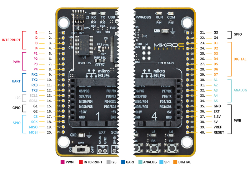
MIKROE’s mikroBUS standardizes pinning for multiple functions including analogue, SPI, UART, I2C, a reset signal, interrupt, PWM, and power giving access to over 400 boards that support the standard. Additional resources include more than 1300 Click Boards, incorporating functionality such as sensor inputs, wireless connectivity, rotary encoders, and external memory.
Rapid firmware development and debugging
Toshiba’s MCU Motor Studio supports the Clicker 4 with firmware solutions for sinewave commutation and vector-oriented control for several motor types including BLDC. Using the Clicker 4’s high-speed UART/USB interface, Toshiba’s motor control PC tool allows parameters to be configured as well as providing drive control, real-time logging, and diagnostics.
A total of three control schemes are available - speed, torque, and precise position – all of which can be implemented with or without sensors. In each mode one primary parameter is controlled by adjusting the others. Current detection can be single- or triple-shunt and, used in conjunction with the position control mode, better performance than a Hall sensor can be achieved – in fact, performance can be close to that of a high-precision encoder.
Several functions are available, that simplify porting to other M4K hardware or MCUs. Essential to the control algorithm, a Zero Current Point detector calibrates the ADC with no current applied to the motor while Stop Control offers various MOSFET-controlled braking schemes.
Safety is important in all motor applications and multiple fault protection mechanisms are inbuilt including overcurrent, overvoltage, undervoltage, overtemperature, and motor disconnection detection.
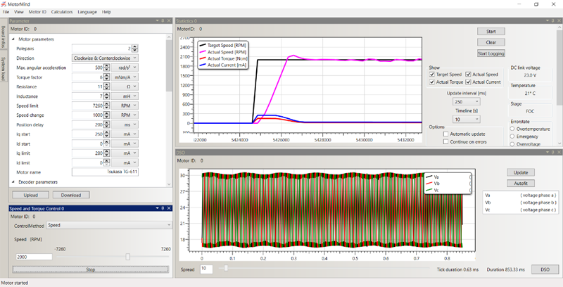
When debugging, the firmware cannot be halted to examine the state of registers and memory. However, software-based digital storage oscilloscope (DSO)-like functionality is available to observe the internal operation of the control algorithm and sensor data (target and actual speed, torque and current) can be monitored with the Motor Control PC Tool. The data is output via the UART and the ‘software DSO’ is able to observe internal registers – something a traditional hardware device cannot do.
Motor drive, configuration and control
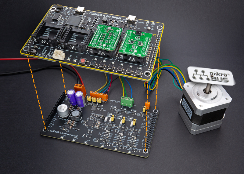
The Clicker 4 Inverter Shield is a three-phase inverter is based upon a 60V gate driver and Toshiba’s low RDS(ON) SSM6K819R MOSFETs that interfaces to any motor and sensor. The board includes an analogue output temperature sensor and an incremental encoder interface as well as a CAN transceiver. Simple jumpers allow rapid configuration of features.
Click image to enlarge
Figure 2: The inverter shield is designed to be used alongside the Clicker 4
Click image to enlarge
Figure 3: Easily accessible MCU pins allow for expansion
The Motor Control PC Tool allows firmware and motor to be matched, compiling and downloading of the firmware to the MCU, then defining motor characteristics via a GUI. The GUI is also used to configure the PI controller and PWM frequency while settings such as shunt and deadtime are configured directly in the firmware. GUI settings can be uploaded live to the Clicker 4 and once debugged, exported as a new header file using the PC tool.
Click image to enlarge
Figure 4: The GUI offers intuitive configuration and monitoring
Summary
Developers are constantly challenged to find ways to deliver smaller and more efficient solutions, leading them to look for tools that will ease development and reduce design risk. The Clicker 4 and Inverter Shield combination provide an easy-to-use, low-cost means of developing solutions around Toshiba’s M4K family of MCUs.