Author:
Tom Ohlsen, Tektronix
Date
08/01/2018
 PDF
PDF
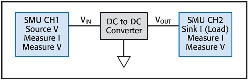
Figure 1. The use of one SMU channel on the input terminal and another on the output terminal replaces several instruments.
In today’s fast paced world of electronics design, complexity represents evil and must be avoided at all cost while simplicity represents all that is right and good. Ok, maybe it’s not quite that extreme, but when it comes to test and measurement, simplicity is the engineer’s best friend because it saves time and effort and yields more consistent and accurate measurement results.
One instrument that maximizes simplicity for many common measurements is the source measurement unit (SMU), which combines a power supply, a digital multimeter, current source and electronic load in a single box. This results in a test instrument that is more versatile than the individual instruments are alone, simplifies test setups and reduces measurement steps as well as the potential for error.
Rather than spend a lot of time trying to explain how an SMU simplifies measurements, it might be easier to show by example. To that end, here we first look at how to simplify DC-DC converter characterization with an SMU followed by techniques for simplifying FET device testing with an SMU. As these examples illustrate, working with an SMU takes fewer step and delivers critical measurement insight.
Simplifying DC-DC converter characterization
Like any device, DC-DC converters need to be characterized by manufacturers and by engineers evaluating them for a design. Given the increased pressure to develop products that consume less power, design engineers are looking for ways to increase power conversion efficiencies. Numerous measurements are required to characterize the electrical parameters of DC-DC converters. Tests include:
· Line regulation
· Load regulation
· Input and output voltage accuracy
· Quiescent current
· Efficiency
· Turn-on time
· Ripple
· Transient response
Typically, electrical characterization of DC-DC converters involves sourcing and measuring input voltage (VIN), measuring input current (IIN), measuring the output voltage (VOUT), and sinking a load current (IOUT). From these measurements, the efficiency and other parameters can be determined. The efficiency is important for most designs, especially battery-powered products, because it directly affects the running time of the device.
Traditionally, the DC characterization of these devices required the use of a couple of digital multimeters, a power supply, and an electronic load. However, the DC characterization can be simplified by replacing all of these electronic instruments with a single two-channel SMU. SMUs are well-suited for testing a wide variety of I-V parameters of DC-DC converters because they can source and measure both current and voltage, as well as function as an electronic load. Note that to complete the full range of DC-DC converter tests, an oscilloscope is required with the SMU providing input voltage and the load current.
Using one instrument rather than multiple units simplifies the test implementation, software, and synchronization, as well as taking up less rack or bench space. As shown in Figure 1, using one SMU channel (CH1) on the input terminal and another SMU channel (CH2) on the output terminal of the DC-DC converter replaces several instruments.
DC-DC converter characterization involves testing many electrical parameters. We'll focus on load regulation and line regulation because they're among the most commonly performed tests.
Load Regulation
Load regulation refers to a DC-DC converter's ability to maintain the specified output voltage as the load current (ILOAD) varies under a constant VIN. Typically, the load-regulation test is performed over the entire range of load currents.
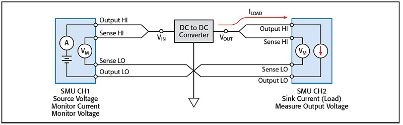
Figure 2 shows a typical load regulation test setup using two SMU channels. SMU CH1 supplies the input voltage and monitors the input current. SMU CH2 is configured as an electronic load by setting it to sink current (source a negative current). In this mode, the SMU instrument will operate in the fourth quadrant and sink current.
Click image to enlarge
Figure 2. This is a typical load regulation test setup using two SMU channels.
The SMU channels are configured using the remote sense, or four-wire, connection. Using a four-wire connection eliminates the lead resistance that would otherwise affect measurement accuracy. With the four-wire method, the source outputs using one pair of test leads (between Output HI and Output LO), and the voltage drop is measured across a second set of leads (across Sense HI and Sense LO). Connect the sense leads as close to the device as possible, which will minimize lead resistance from adding to the measurement.
Figure 3 shows the results of a typical load regulation test in which the DUT was configured to output a constant 3.6V. SMU CH1 was set to bias 5 V (nominal value) to the voltage input terminal. SMU CH2 was configured to sweep a load current from 0 to 1 A and measure the resulting output voltage. Measurements were taken under software control. The load regulation percentage can be easily calculated from the I-V data.
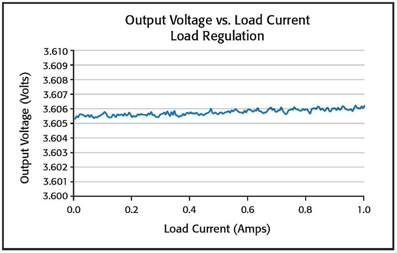
Click image to enlarge
Figure 3. Here is the result for a typical load regulation test.
Line Regulation
Line regulation refers to a DC-DC converter’s ability to maintain the specified output voltage in response to input voltage changes. The output voltage should remain constant, within a few millivolts, while the input voltage is varied over the specified voltage input range. For the line regulation test, both SMU channels are connected to the DC-DC converter in the same way they were for the load regulation test.
However, for this test, the input voltage is swept over the specified input voltage range and the output voltage is measured. The load current is typically set to 0 A. Figure 4 shows the result from a typical line regulation test. One channel of the SMU instrument (SMU CH1) was configured to sweep voltage on the input terminal of the device while the other (SMU CH2) was configured to measure the output voltage. The line regulation percentage can then be calculated from the I-V data.
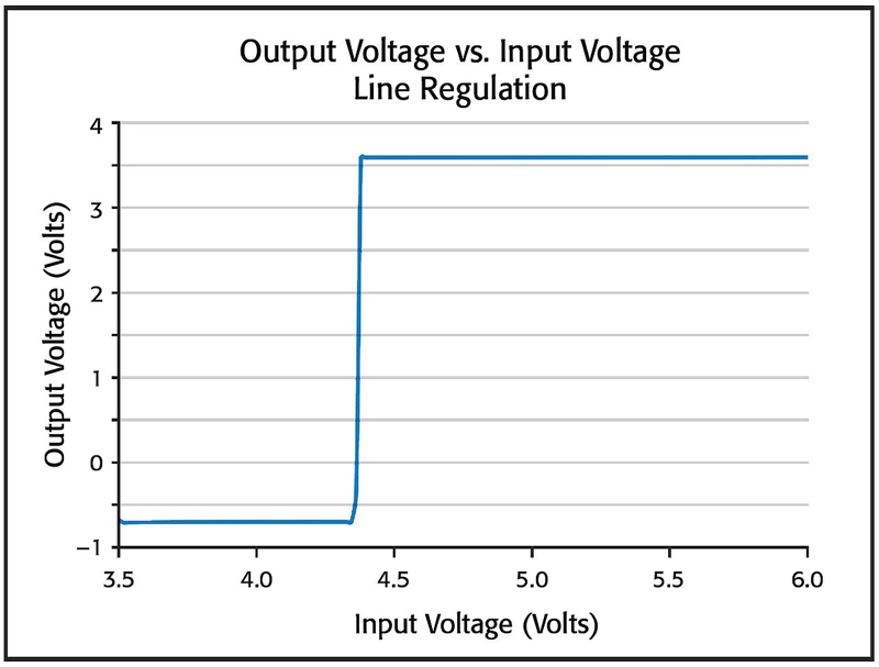
Click image to enlarge
Figure 4. This shows the result for a typical line regulation test.
Simplifying FET testing with SMUs
Characterizing an FETs current-voltage (I-V) parameters is crucial to ensuring it meet specifications and works properly in its intended applications. These I-V tests may include gate leakage, breakdown voltage, threshold voltage, transfer characteristics, drain current, on-resistance, etc. FET testing often involves programming and synchronizing several instruments, including a sensitive ammeter and multiple voltage sources, which can be tedious and time consuming. Although a turnkey semiconductor characterization system solves the integration problem, systems of this type typically cost tens of thousands of dollars. A third approach involves using SMUs. The number of SMUs required in the test usually depends on the number of FET terminals that must be biased and/or measured.
An FET is a majority charge-carrier device in which the current-carrying capability is varied by an applied electric field. It has three main terminals: the gate, the drain, and the source. A voltage applied to the gate terminal (VG) controls the current that flows from the source (IS) to the drain (ID) terminals.
There are many types of FETs, including MOSFET (metal-oxide-semiconductor), MESFET (metal-semiconductor), JFET (junction), OFET (organic), GNRFET (graphene nano-ribbon), and CNTFET(carbon nanotube). These FETs differ in the design of their channels.
An FET’s I-V characteristics can be used to extract many device parameters, to study the effects of fabrication techniques and process variations, and to determine the quality of the contacts. Figure 5 illustrates a DC I-V test configuration for a MOSFET using a two-channel SMU (CH1 and CH2). Here, the Force HI terminal of SMU CH1 is connected to the gate of the MOSFET and the Force HI terminal of SMU CH2 is connected to the drain. The source terminal of the MOSFET is connected to the Force LO terminals of both SMU channels or to a third SMU channel if it is necessary to source and measure from all three terminals of the MOSFET.
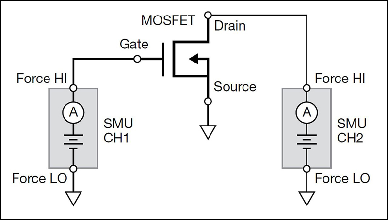
Click image to enlarge
Figure 5. This is a DC I-V test configuration for a MOSFET using a two-channel SMU.
Once the device is set up and connected to the SMU, the control software, often an embedded software tool, must be configured to automate the measurements. After connecting the instrument to any computer with an Ethernet cable, entering the IP address of the SMU into the URL line of any web browser will open the instrument’s web page. From that page, the user can launch the embedded software and configure the desired test or tests, which can often be saved and recalled for future use.
One I-V test commonly performed on a MOSFET is the drain family of curves (VDS-ID). With this test, SMU CH1 steps the gate voltage (VG) while SMU CH2sweeps the drain voltage (VD) and measures the resulting drain current (ID). Once the two SMU channels are configured to perform the test, the data can be generated and plotted on the screen in real time. Figure 6 shows a MOSFET drain family of curves created by using a two-channel SMU optimized for low current measurements. Once exported to a .csv file, this I-V data can be imported into a spreadsheet for further analysis or displayed in table view.
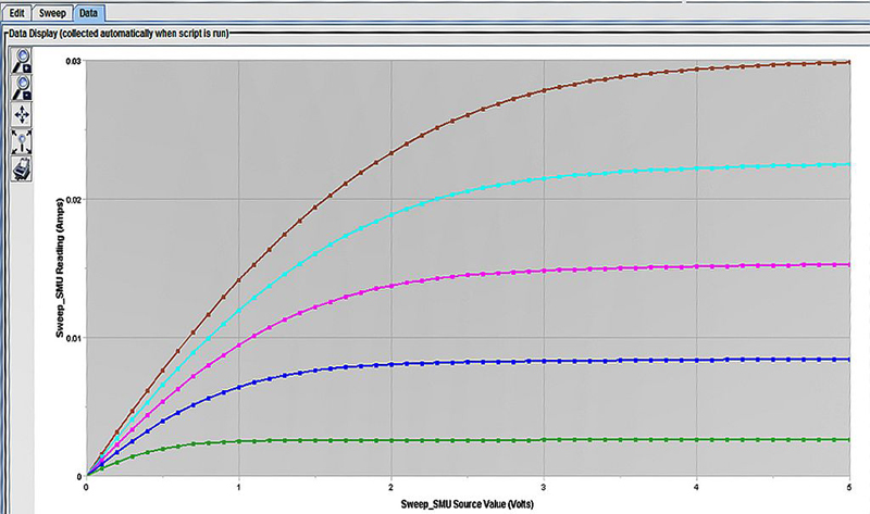
Click image to enlarge
Figure 6. This MOSFET drain family of curves was created using a two-channel SMU optimized for low current measurements.
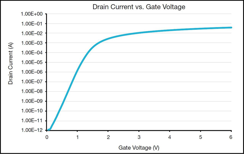
Another common I-VFET test this same configuration supports is Drain Current (ID) as a function of Gate Voltage (VG). For this test, the gate voltage is swept and the resulting drain current is measured at a constant drain voltage. Figure 7 shows the results of an ID-VG curve at a constant drain voltage. However, in this case, the generated data was exported to a file and plotted on a semi-log graph. This test can be easily reconfigured to step the drain voltage as the gate voltage is swept. The ID-VG data shows the many decades of drain current that the SMU measured, from 1E-12 to 1E-2 amps.
Click image to enlarge
Figure 7. In this example, drain current is shown as a function of the gate voltage of a MOSFET.
Summary
Test complexity is the enemy of engineering efficiency and productivity. As shown here, source measure units that combine the functionality of multiple instruments into a single box can simplify testing procedures, saving time and producing more accurate and repeatable results. In the case of DC-DC converter testing, a single two-channel SMU replaces a couple of digital multimeters, a power supply, and an electronic load. In the case of the FET characterization, SMUs are a simpler, cost-effective alternative to test setups such as sensitive ammeter and multiple voltage sources or a dedicated semiconductor characterization system.
Tektronix