An isolated ADC with integrated DC-DC converter
Measuring high voltages (12V to 300V) and currents using a low-voltage microcontroller is a growing requirement in industrial automation equipment. For example, a low- voltage microcontroller system can be used to monitor high-voltage industrial equipment for an unstable AC or DC power supply. This protects equipment against surges and overloads and allows diagnostic testing of fail-safe equipment in electrically noisy environments.
Successfully interfacing high-voltage circuitry to low-voltage circuitry requires locating a block of isolation circuitry at the interface. In this design solution, we’ll outline a new approach to data and power isolation that protects equipment and operators from high voltage concerns, while reducing cost and design footprint.
Measuring high voltage safely
High voltage measurement presents a safety concern for operators of industrial equipment. To ensure that the equipment is safe to use, it is necessary to introduce galvanic isolation between the high voltage “field-side” and the low voltage “logic-side” circuits. The isolation barrier ensures that no direct conduction path exists between the two sides, thereby preventing current from accidentally reaching ground via a human body.
It also protects the low-voltage logic-side circuitry from the high field-side voltages and eliminates noise and ground loops between the two sides, which can cause errors in the voltage and current measurements. Traditionally, transformers are used for power isolation and optocouplers (or digital isolators) are used to create the data isolation barrier. Although effective, this traditional “discrete” isolation approach is costly to implement and requires a significant amount of space.
Typical high-voltage monitoring circuit
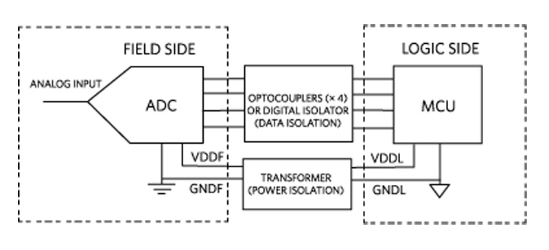
A functional block diagram for a typical high-voltage monitoring application is shown in Figure 1. An analog-to-digital converter (ADC) samples the high field-side voltage and generates a digital output in the form of a four-wire Serial Peripheral Interface (SPI). This field-side digital signal is transmitted to the logic-side microcontroller unit (MCU) via the digital isolator circuitry which is located between the ADC and the MCU. A disadvantage of this configuration is that the isolator circuitry requires its own separate power-supply routing while also consuming valuable board space.
Click image to enlarge
Figure 1. Typical data and power isolation in a high voltage monitoring system
Integrating the Isolation
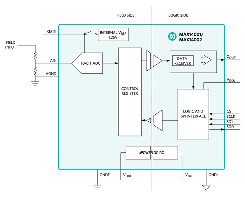
Clearly, if the field-side and isolation circuitry were located in a single package, power routing could be simplified and board space requirements could be reduced. Conveniently, such a solution is available in the form of the MAX14001 isolated ADC. A simplified functional diagram of the MAX14001 is shown in Figure 2. It integrates a single-channel, 10-bit successive approximation register (SAR) with CMOS capacitive digital isolation circuitry which allows a digital signal to be accurately transmitted between two electrically isolated domains via a capacitive dielectric. This provides up to 3.75kVRMS between the field-side and logic-side of the devices.

Click image to enlarge
Figure 2. MAX14001 simplified functional diagram
The MAX14001 also includes an integrated isolated micropower DC-DC converter to provide power to the field-side circuitry. Thus, a single-supply voltage (VDD) can be used to provide power to both the field-side and logic-side circuitry while still maintaining isolation between both sides. The field-side voltage (VDDF) is provided as a nominal 3V output with enough current for additional low current (70 µA) circuitry, such as an external voltage reference.
Line voltage monitoring
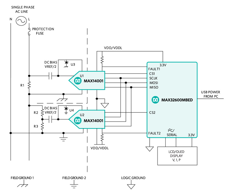
Figure 3 illustrates how a practical high-voltage and current monitoring system can be created by interfacing two MAX14001 devices to a MAX32620 microcontroller. In this example, the voltage being monitored is an AC ‘mains’ voltage. The ‘current monitoring’ ADC (U1) measures the voltage across a small sense resistor (R1) to obtain the current flowing in the live wire. The ‘voltage monitoring’ ADC (U2) uses a voltage divider (R2–R3) across the load to step down the input voltage to the ADC for measuring the high voltage on the AC line.
Click image to enlarge
Figure 3. AC voltage/current line monitoring circuit
The ADC is a free-running converter, sampling at ~10ksps, that continuously updates the data register for each new conversion. Since the line voltage is either 50Hz or 60Hz, this sample rate easily meets the Nyquist criteria. Although the two ADCs are not synchronized, the reading can be considered to be almost simultaneous given the relatively high sample rate.
The ADC readings are transmitted to the microcontroller by the SPI interface. Average power, power factor, frequency and total power consumption of the AC line can be calculated from the current and voltage data output from the two ADCs.
A unique feature of the MAX14001 is the integration of a binary comparator with programmable upper and lower thresholds, which provides real-time monitoring of the field-side input voltage. This makes it ideal for safety or diagnostic applications where fast response is critical. The binary comparator output (COUT) is driven high when the input voltage is above the upper threshold and low when it is below the lower threshold.
The response time of the comparator to an input change is less than 150μs with filtering disabled. By counting the zero crossings of the comparator output, the AC frequency can be easily calculated by the microcontroller. Real-time AC line quality values can be displayed by connecting the microcontroller to an LCD.
No separate isolation
A significant advantage of using the MAX14001 isolated ADC is that there is no need for separate isolation circuitry or a field-side power supply, greatly simplifying the design and reducing cost, complexity and board space.
To ensure equipment safety, high-voltage and current monitoring systems have traditionally included a field-side sampling ADC and a logic-side MCU with a discrete block of isolation circuitry connecting the two. This has implications for the system designer in terms of cost, complexity, and board space requirements.
By integrating digital isolation circuitry into a single package along with a 10-bit ADC, a device like the MAX14001 can afford designers the opportunity to reduce the footprint and the bill of materials of industrial monitoring systems. The MAX14001 is suitable for use in a broad range of applications including distribution automation, substation automation, industrial control (multi-range, digital input modules with individually isolated inputs), as well as applications requiring high-voltage binary inputs.