Simplifying System Design Through a Bidirectional Power Delivery Solution Up to 140 W

How an integrated USB-C PD MCU coordinates power-path control, system monitoring, and application functions
1. Why bidirectional USB-C changes the design problem
The drawer full of obsolete chargers has become a recognizable symbol of fragmented power interfaces. The European Commission estimates that discarded and unused chargers account for approximately 11,000 tons of electronic waste annually. Its common-charger rules now establish USB-C as the charging port for a wide range of portable electronics, extending to laptops from April 28, 2026.
A dual-role, battery-based design must coordinate USB PD communication, source and sink power paths, battery charging, power conversion, and application control. Integrating the PD controller, bidirectional gate driver, programmable MCU, and measurement resources reduces the number of separate devices and interfaces required to manage these functions.
EZ-PD™ PMG1-S4 addresses this challenge by supporting USB PD 3.2 operation up to 140 W across an input and output voltage range of 4 V to 28 V. These specifications extend USB-C PD into higher-power embedded products. Its bidirectional NFET gate driver enables the same power path to operate in source or sink mode, supporting products that receive power for battery charging and supply power when the application requires it.
One design option is to distribute USB PD communication, power-path control, monitoring, and application processing across several components, but a more effective approach is to coordinate these functions through a programmable controller. PMG1-S4 combines USB-C PD functionality with an Arm® Cortex®-M0+ processor and programmable analog and digital resources. This brings power negotiation, bidirectional switching, monitoring, and product-specific control into one programmable design domain.
2. Bringing bidirectional power under one controller
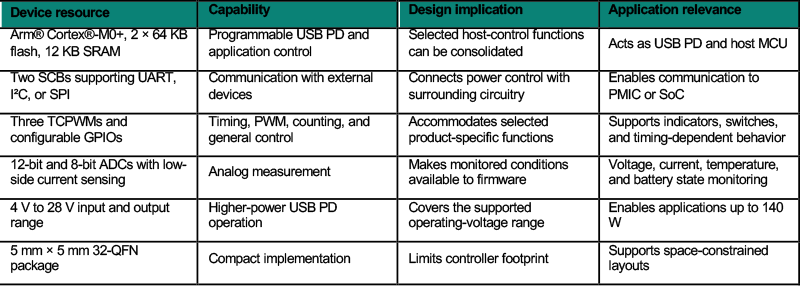
The traditional dual-role port design is a PD controller controlling separate source and sink back-to-back MOSFETs to either operate in the power source mode or sink mode. There is an additional MCU controlling the buck-boost charger to handle battery management and system peripheral control, and an additional DC-DC converter to offer sourcing capability when Type-C acts as the source role. PMG1-S4 brings these responsibilities together. PMG1-S4 has an integrated bidirectional NFET gate driver simplifying two independent back-to-back MOSFETs into one by working with a bidirectional buck-boost charger. The device combines a USB-C PD controller with a programmable 32-bit Arm® Cortex®-M0+ processor, 2 × 64 KB of flash, 12 KB of SRAM, and programmable analog and digital blocks. This can further reduce additional host MCUs in the system that would have been needed to handle system peripheral control.
Controlling both directions through one power path
At the power-path level, PMG1-S4 integrates a bidirectional NFET gate driver. It controls the USB-C PD port as either a power source or a power sink using the same external power path. The device also integrates a high-voltage LDO and dead-battery Rd functionality for battery-powered applications.
Together, these features support a coordinated bidirectional architecture. The NFET gate driver controls power flow in either direction, while dead-battery Rd allows the USB-C port to present the required sink termination when the product cannot initially power the controller. The integrated high-voltage LDO supplies the device from VBUS.
Source and sink operation impose different conditions on the external switches, battery, and application. Placing USB PD negotiation, power-path control, and programmable decision-making in one device gives the design a common point from which these transitions can be managed.
Monitoring the power path
PMG1-S4 includes a low-side current-sense amplifier, a 12-bit ADC, an 8-bit ADC, and high-voltage protection circuits. These resources allow electrical measurements to inform charging, power delivery, and fault-response behavior. Because sensing, processing, and USB PD control reside in the same device, firmware can link monitored conditions directly to the active power role without transferring information between a standalone PD controller IC and a host MCU.
Connecting power delivery to the application
PMG1-S4 includes two serial communication blocks supporting UART, I²C, or SPI, three timer/counter/PWM blocks, and configurable GPIOs. These resources can connect USB-C power behavior with surrounding control circuitry, indicators, switches, and timing-dependent functions. Selected application functions can therefore share the same programmable environment as USB PD control.
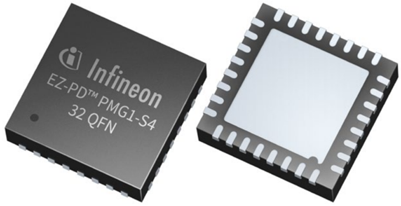
The device supports input and output voltages from 4 V to 28 V and comes in a 5 mm × 5 mm 32-QFN package with a 0.50 mm pitch. It supports an ambient operating range of −40°C to 85°C and a maximum junction temperature of 125°C. The voltage range supports applications up to 140 W, while the compact package helps limit the PCB area occupied by the central controller.
The voltage range supports USB PD applications up to 140 W, while the compact package helps limit the PCB area occupied by the central control device. Suitability for a particular product depends on the complete electrical and thermal design, including the external power path, power-conversion stage, protection strategy, and operating environment.
Click image to enlarge
Figure 2: EZ-PD™ PMG1-S4 in a compact 32-QFN package for integrated USB-C PD and application control
3. One port, two directions of power flow
Click image to enlarge
Table 1: Relationship between key EZ-PD™ PMG1-S4 resources, capabilities, and application relevance
In a power bank, bidirectional USB-C operation is expected: the port receives power to charge the internal battery and later supplies power to another device. The same capability can serve power and garden tools, smart speakers, and vacuum cleaners.
PMG1-S4 targets these applications with support for USB PD 3.2 up to 140 W and a bidirectional NFET gate driver that controls source and sink operation through the same power path.
Consider a cordless power tool. When connected to a compatible supply, the USB-C port operates as a sink and receives power for charging. If the product is designed to provide power externally, the port can assume the source role and draw energy from the battery. Both use cases involve the same connector and external power path, but require different negotiated contracts, switch states, monitored conditions, and application responses.
Firmware can define when source operation is available and how the product responds to monitored conditions. A product may permit power output only when sufficient battery capacity is available or determine its output capability from battery status. The precise strategy depends on the battery system, power-conversion topology, and product requirements.
Evaluating the PD contract, power-flow direction, electrical measurements, and application state within the same programmable environment allows the USB-C port to become an active part of the product’s power-management strategy.
4. From device integration to application development
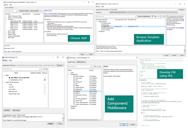
PMG1-S4 design is supported by the ModusToolbox™ development environment, a board support package, the EZ-PD™ PMG1 software development kit, and evaluation boards. Together, these resources provide a common environment for USB PD and application firmware development.
The interoperable USB-C PD stack provides the protocol foundation, allowing development to focus on product-specific behavior. This may include defining supported power roles, coordinating the external power path, processing monitored conditions, communicating with surrounding circuitry, and linking USB-C operating states to application functions.
This environment is particularly useful when PMG1-S4 replaces a standalone USB PD controller and selected host-MCU functions. Commands, measurements, status information, and fault responses can be processed within a shared software architecture rather than exchanged between separate controllers.
A common hardware platform can also be adapted through firmware for related product variants, provided their electrical and processing requirements remain within the device’s capabilities. Evaluation hardware allows USB PD behavior and application functions to be assessed together before the architecture is committed to a product design.
Explore device information and development resources at https://www.infineon.com/promo/ez-pd-pmg1-s4.
Click image to enlarge
Figure 3: Eclipse IDE for ModusToolbox™ resources and middleware supporting PMG1 MCU application development
5. Coordinating bidirectional USB-C power
Higher-power bidirectional USB-C requires PD negotiation, power-path control, electrical monitoring, and application behavior to work together.
PMG1-S4 combines USB PD 3.2 support up to 140 W with a bidirectional NFET gate driver, Arm® Cortex®-M0+ processor, and integrated sensing and communication resources. This gives products a common control environment for receiving, directing, and monitoring power.
This integration allows the product to respond coherently when power conditions change. The negotiated contract, direction of power flow, monitored conditions, and selected application functions can be coordinated without dividing the decisions among separate controllers.
For power and garden tools, power banks, smart speakers, vacuum cleaners, and other suitable embedded products, this provides a practical foundation for making USB-C an active part of the product’s power architecture.
This article was developed with AI assistance.
References
1. European Commission, “EU common charger rules: Power all your devices with a single charger,” December 28, 2024. https://commission.europa.eu/news-and-media/news/eu-common-charger-rules-power-all-your-devices-single-charger-2024-12-28_en
2. European Commission, “One common charging solution for all.” https://single-market-economy.ec.europa.eu/sectors/electrical-and-electronic-engineering-industries-eei/radio-equipment-directive-red/one-common-charging-solution-all_en
3. Infineon Technologies AG, EZ-PD™ PMG1-S4: Single-port bidirectional source/sink USB-C PD MCU, product brief. https://www.infineon.com/assets/row/public/documents/24/45/infineon-pmg1-s4-product-brief-en.pdf
4. Infineon Technologies AG, AN232553: Getting started with EZ-PD™ PMG1 MCU on ModusToolbox™ software, Rev. C, February 14, 2024. https://www.infineon.com/row/public/documents/24/42/infineon-an232553-getting-started-with-ez-pd-pmg1-mcu-on-modustoolbox-software-applicationnotes-en.pdf