Smart Activation circuit protection in li-ion battery applications
As high-power applications switch to Li-ion batteries, a protection method for ratings over 30 VDC emerges
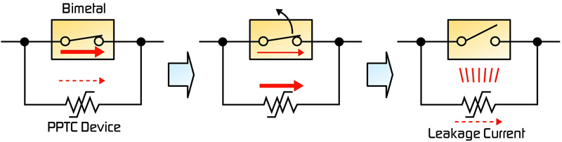
Figure 1: The activation steps of the MHP device
Li-ion technology with smaller, lighter-weight, and higher-power batteries is now replacing nickel-cadmium or lead-acid batteries in high-discharge-rate battery applications. Meanwhile, more high-power applications are switching to Li-ion batteries, which create a need for more robust circuit protection to ensure safety in battery-powered products. Currently, few protection systems address high-discharge-rate Li-ion battery applications, such as power tools, E-bikes, LEVs (light electric vehicles) and standby-power applications. Traditional circuit-protection techniques also tend to be large, complex, and expensive. MHP (metal hybrid polymeric) technology addresses the Li-ion battery-pack market trends by offering a cost-effective, space-saving circuit protection device. Connecting a bimetal protector in parallel with a PPTC (polymeric positive temperature coefficient) device, the MHP device provides resettable overcurrent protection using the PPTC device's low resistance to help prevent arcing in the bimetal protector at higher currents. Core design concept During normal operation of an MHP, current passes through the bimetal contact due to its low contact resistance. When an abnormal event occurs, such as a power-tool rotor lock, the tool's motor draws more current, causing the bimetal contact to open. At this point, the current shunts to the lower resistance PPTC device, which prevents arcing between the contacts while also heating the bimetal, keeping it open and in a latched position (Figure 1). The activation steps of the MHP device include: 1. During normal operation, because contact resistance is very low, most of the current goes through the bimetal. 2. When the contact begins to open, resistance increases quickly. If the contact resistance is higher than the PPTC device's resistance, most of the current goes to the PPTC device and no — or less — current remains on the contact, preventing arcing between the contacts. When current shunts to the PPTC device, its resistance rapidly increases to a level much higher than the contact resistance and the PPTC device heats up. 3. After the contact opens, the PPTC device heats up the bimetal and keeps it open until the over-current event ends, or power is turned off. An PPTC device's resistance is much lower than that of a ceramic PTC, so even when the contact opens a small amount, resistance increases only slightly, and the current shunts to the PPTC device to help prevent contact arcing. Typically, resistance ratio at room temperature between ceramic and polymer PTC devices is in the range of 100:1, so higher resistance ceramic PTC devices combined in parallel with a bimetal are less effective at suppressing arcs at higher currents than MHP devices.
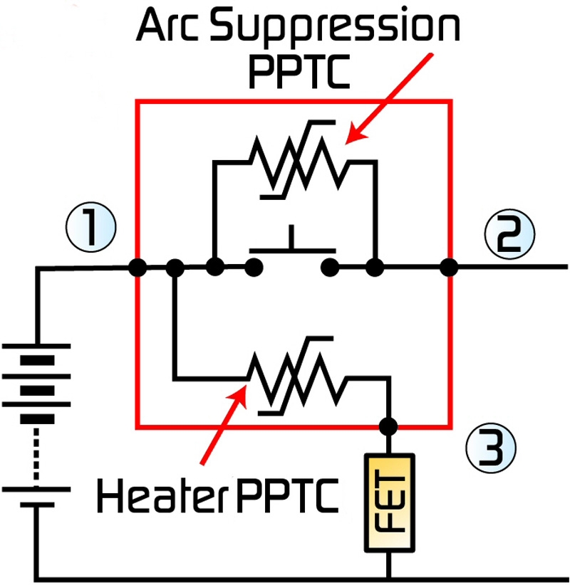
Smart activation Smart-activation devices are the latest generation technology and incorporate a third terminal as a signal line for over-charge protection. This allows the device to take advantage of battery-monitoring ICs advanced features. When the IC detects an abnormality, it sends a signal via a low power switch line to activate the smart-activation device and open the main line (Figure 2). The activation steps are: 1. The IC monitors the battery for temperature, current, and voltage abnormalities. 2. The switch is ON at an abnormal event (1?3). 3. The PPTC heater activates and heats bimetal. 4. The contact opens and cuts contact to the main line (1?2).
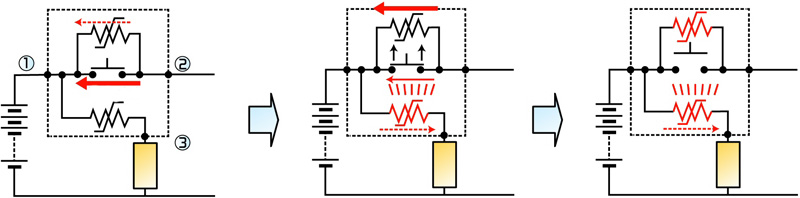
Figure 3 shows an example of the overcharge-protection concept and activation steps for a 50 A, 400 VDC device with a hold current of 50 A on the main line. Here the IC monitors individual cell voltage, the FET turns on during an abnormal voltage event, the heater PPTC activates and heats the bimetal, the contact opens and cuts the current to the main line. The smart-activation device's benefits include: • Over-charge protection in battery packs • External activation allowing the device to use the battery-monitoring IC to detect voltage, current, and temperature faults and trigger the device • Resettable device; no need to overrate for inrush current • Smaller size, thinner form factor compared to fuses or other breaker devices • Arc-suppression PPTC design suppresses arc at contacts • Low power switch line opens main line; uses a lower cost FET
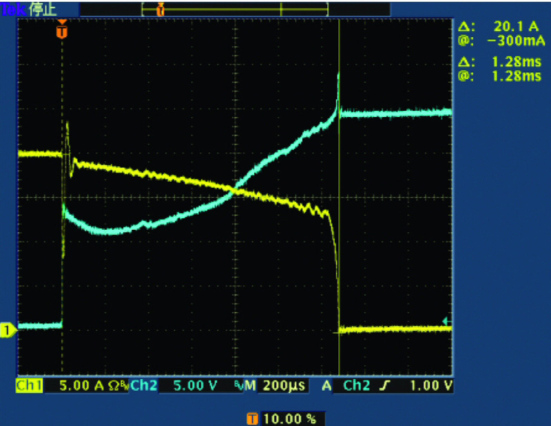
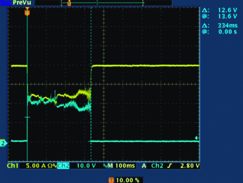
Arcless contacts Figures 4a and 4b show current and voltage using only a bimetal protector. Figure 4a shows typical results of the open bimetal protector at a rated voltage of 24 VDC and 20 A. It opens in 1.28 ms. Figure 4b depicts double the rated voltage of the bimetal protector. A standard bimetal protector arcs under fault conditions and the time from when contact starts to open to welding of the short circuit is 334 ms.
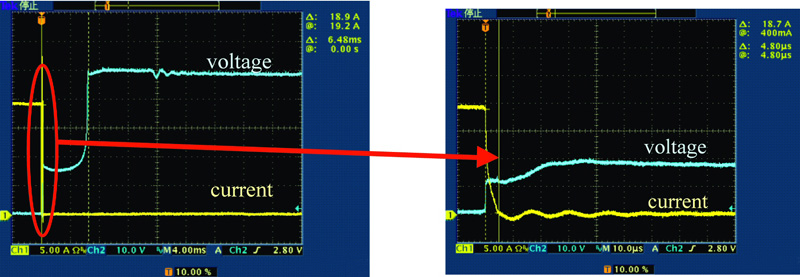
Figures 5a and 5b show the result of combining a PPTC device and bimetal in parallel in which current is clearly cut off. Figure 5a shows the time lapse between when the bimetal protector starts operating, until the PPTC device fully activates is 6.48 ms. Figure 5b shows the time from the protector operating until current cut off is 4.80 μs, when the applied voltage is twice the rated voltage. This succession of images demonstrates the smooth transfer from bimetal protector to the PPTC device with no welding of protector contacts, and shows how the PPTC device protects the contacts from arcing. www.te.com


