You deserve the full picture
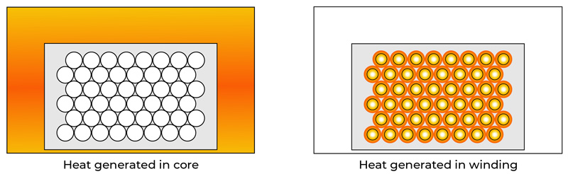
Figure1: Inductor Self-heating in the core vs the winding
Smart Consideration of Inductor Thermal Performance for DC-DC Converter Performance and Reliability
The efficiency and the thermal properties of key components have very real implications for the success of any converter design. Switching FETs and inductors are generally the two most considered choices determining size and performance of any converter. Though made of vastly different materials of course, and with different circuit functions to perform, FETs and inductors do have a very important characteristic in common when it comes to efficiency/power loss. That is, for FETs and inductors alike, both conduction (static) losses and switching (dynamic) losses must be considered.
Converter designers know inductor data sheets are well covered with current “ratings”, with multiple columns for Isat, Irms and DC resistance. And yet, the most experienced designers are also aware that despite the consistent appearance of all those numbers, they primarily address inductor conduction losses but rarely give necessary information about dynamic switching losses. This article will focus on the limitations of Irms and DCR and other factors that have important implications for thermal performance that are often not covered by the datasheet.
FET Losses
Whether a switch is a traditional silicon MOSFET or GaN or SiC, we know conduction, switching, and gate drive losses must all be considered. All of these have been studied in depth and are well characterized. Suppliers provide a variety of datasheet curves, calculation guides, and online tools to calculate application performance.
The different types of FET losses are all generated from roughly the same place in the FET and thermal properties are characterized by junction-to-case thermal resistance. Strictly speaking, FET losses don’t all come from a single junction or point, but they are all generated on the die and heat generated is conducted to the package exterior through a homogenous packaging material. One would expect similar thermal properties for FETs that share a given die size and package.
Inductors
Like FETs, inductors exhibit conduction loss as well as a multiplicity of dynamic losses which include core and winding losses. Dynamic winding losses include skin effect and proximity effect, which is particularly challenging to model and predict, given the wide variety of possible winding configurations. Consider the windings shown in Figure 1, which represent the different windings for two different inductance values within the same inductor series using the same core/package. The first thing to be seen is that the winding and core occupy significantly different spaces within the overall volume of the inductor. Whereas we can predict the likely heat conduction paths from a FET die through the packaging material to the package surface, for an inductor it is not quite so straightforward since any heat conduction path will depend on the source of the heat.
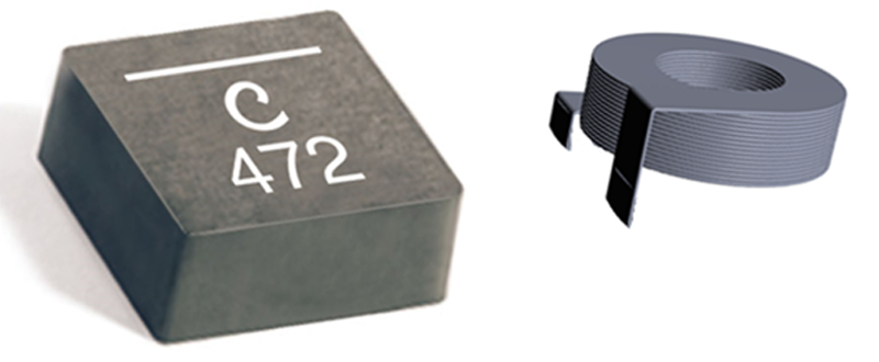
Figure 1 helps visualize how heat generated within an inductor varies spatially throughout the inductor body depending on the specific loss mechanism. It also makes clear that traditional coil windings on shaped cores are not the best for removing heat, especially if the heat is primarily generated by the winding, because there is often minimal or no direct surface area contact between the winding and surrounding core. Note that popular composite core inductors, however, in which the core material is molded over, in, and around the windings create a much better path for thermal conduction from inside to outside the inductor. (Figure 2).
Click image to enlarge
Figure 2: Molded composite-core inductor
Design Example – Getting Started
A typical datasheet provides multiple pieces of data to help determine inductor temperature rise due to operational self-heating.
Click image to enlarge
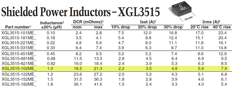
Figure 3: Performance specifications for Coilcraft's XGL3515-102ME power inductor
Let’s consider selecting an inductor for a 24 V-5 V converter to deliver 8 A dc load current at 2.2 MHz switching frequency. To start we calculate the desired inductance value using

and calculating for 30% ripple current

which results in L = .79 µH. We choose a standard 1 µH inductor to give some margin and keep the ripple current on the low side. We see from the inductor datasheet in figure 3 that inductor XGL3515-102ME has an Irms rating of 7.8 A for a 40° C self-heating temperature rise. From the Irms and the dc resistance we can calculate the expected power loss = I2R = (82)(.0185) = 1.18 W at maximum load current, which represents something just less than 3% of the 40 W output power. So, what we have achieved is the selection of a very compact inductor measuring only 3.5 mm square by 1.5 mm tall for a maximum temperature rise of about 40° C at full output power.
Is that it?
The example above seems pretty simple and is, in fact, too simple. You have surely noticed that we did not address the possible presence of dynamic inductor loss. The truth is that inductor datasheets don’t address dynamic losses. Some datasheets do include equations for user core loss estimations, but that would not cover winding loss from skin effect, proximity loss, eddy current due to fringing flux, etc. Each of these dynamic inductor loss components can be modeled or calculated.
For instance, core loss can be estimated using the original Steinmetz equation[i] or one of its many derivations. This requires the knowledge of all the core dimensions, the material coefficient for the core material, and the number of turns in the winding. Likewise, proximity effect in the windings can be calculated using Dowell’s equations[ii] or curves. For this, one must know the winding dimensions and conductor properties. For both Steinmetz and Dowell, one must know many details of how an inductor is constructed and the properties of the materials within. All these things are known to an inductor designer, but how is a user to know? How is one to select an appropriate inductor for a specific application and correctly understand its thermal performance? It should be noted that thermal performance is not only an indirect indicator of operating efficiency, but thermal performance is the key thing that can damage an inductor. Simply put, we don’t want inductor self-heating to compromise the reliable life of a converter. While modern inductors are extremely robust and not likely to burn themselves up under most conditions, a heat source in the circuit can easily compromise the expected lifetime of other key components.
The Answer
Tools like Coilcraft’s patented MAGPro® DC-DC Optimizer take over the thermal calculation based on user circuit inputs and eliminate the need for converter designers to dive deeply into the inductor details. The key point is the effective use of commercial, off-the-shelf inductors while still getting the type of insight and performance expectation that used to require one to design their own inductors or at least be deeply versed in their details.
One might wonder how complete the model is to drive such tools. Does the model include all possible parasitic losses? The answer is, the tool is not based on a model but on a real inductor characterization using square voltage (hard switched) converters and capturing the total dc and ac (dynamic) losses. This eliminates the need to accurately predict all possible loss mechanisms because all losses are captured in the measurement/characterization process.
Let’s return to the design example using the Coilcraft MAGPro DC-DC optimizer tool. The process starts by entering the same application inputs.
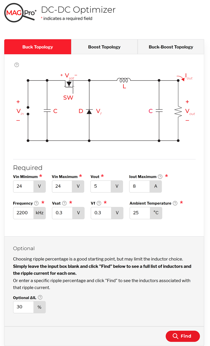
Click image to enlarge
Figure 4: Inputs for DC-DC Optimizer
We select the same 1 µH inductor and the tool tells us the losses are not 1.18 W as calculated from the data sheet, but almost twice that at more than 2.7 W. And rather than the 40° C temperature rise from self-heating, the temperature rise is now expected to be more than twice at 94° C!!
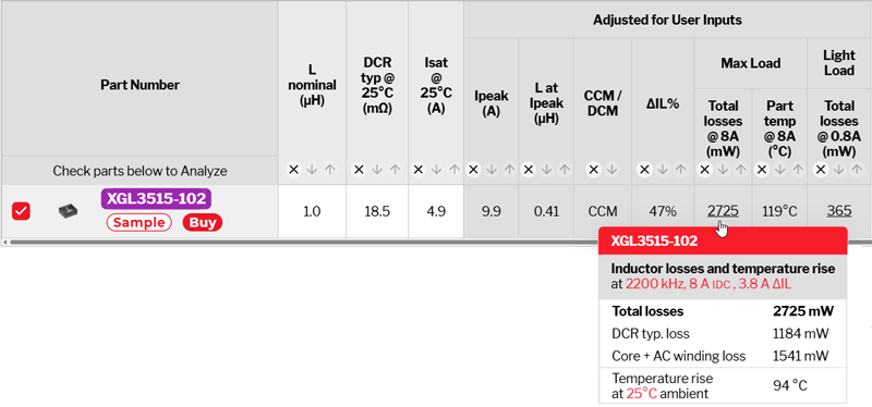
Click image to enlarge
Figure 5: Full picture of inductor loss and temperature
Not only does this information provide a quick answer to the expected temperature rise but also points the way to an improved solution. Knowing that this solution includes mostly dynamic losses suggests that a change of inductance value for lower ripple current, or a change of switching frequency, or even choosing a larger inductor could provide higher efficiency and a cooler running inductor.
Summary
It has been shown that inductor losses are in some ways analogous to switching FET losses in that both devices may exhibit conduction and dynamic loss mechanisms. Due to the physics of magnetics, inductors have their own unique set of physical properties that determine efficiency. Rather than each circuit designer being faced with a long inductor design analysis, tools are available that provide answers based on proven engineering and real-world data and do it in a quick and user-friendly manner. Being a smarter user of inductors seems to be a better use of most designers’ time than rethinking inductor construction for each new project.
i On the Law of Hysteresis, Charles Proteus Steinmetz, American Institute of Electrical Engineers Transactions, vol 9, pp3-64, 1892.
ii Effects of Eddy Currents in Transformer Windings, P.L. Dowell, PROC. IEE, Vol. 113, No. 8, AUGUST 1966