Smart PFC and DC/DC converter system offers optimum efficiency
Digital power is becoming increasingly popular
The efficiency improvement of power converters is one of the major reasons why digital power is becoming increasingly popular. For specific requirements, digital control allows using the best fitted control strategy and comfortable, intricate tweaking of efficiency. This means the power supply can operate in multiple topologies and modes. This is something that cannot be realized by an analog control unit, which only operates in single mode. The power efficiency of AC/DC and DC/DC converters is a non-linear function of their output load level. Therefore, variation of intermediate bus voltage level (IBV) as well as of converter topologies helps increase efficiency for different output power level. This paper shows a smart system consisting of an AC/DC PFC- and DC/DC system providing 230Vac to 12Vdc conversion with power efficiency self-tuning algorithm. The key approaches for optimum system efficiency are dynamic optimization of intermediate bus voltage (IBV) and phase shedding.
Positioning PFC
Off-line power supplies are widely used in every kind of computer, communication, and home appliance equipment. Power-factor-correction (PFC) control schemes have been developed to comply with the EN61000-3-2 standard for input line current harmonic components. In general, a PFC converter will result a lower efficiency and higher harmonic distortion under light load operation conditions. With the continuously increasing power efficiency target by 80 PLUS [1], U.S. Energy Star [2] and Climate Savers [3], it becomes a design challenge for AC-DC PFC technology to improve its power quality as well as efficiency over a wider operating range [4].
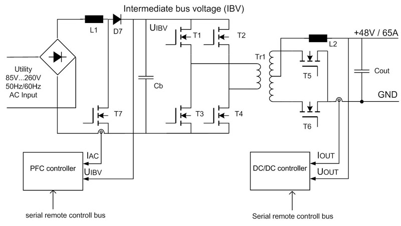
Typically front-end power supply, widely adopted in server and telecommunication systems is shown in Figure 1. The AC input voltage is in range of 85V~240V, while the output voltage 48V is keep constant with high accuracy and low ripple level. The intermediate bus voltage (IBV) in range of 385V is generated to ensure enough headroom for the PFC boost converter in order to ensure low THD-level for wide input voltage range. PFC converters used in server and telecommunication-applications are designed to operate in continuous conduction mode (CCM). When the converter is operating in light load condition, it will operate in DCM condition and the voltage conversion ratio becomes nonlinear as a function of inductor current and input and output voltages, this result increased line current distortion [5].
The inductor peak current will be higher when operating in DCM and results higher switching losses with fixed switching frequency control scheme. One method of reduction the switching power losses during light load is decreasing output voltage.
Fig.1 shows state of the art front-end power supply using one phase digital controlled PFC and digital controlled full bridge forward converter. The PFC controller needs UIBV signal for regulation and IAC signal for protection and telemetry. Similarly, the DC/DC controller uses signals UOUT for regulation and IOUT for protection/telemetry.
Click image to enlarge
Fig. 1: PFC and DC/DC front-end power supply for distributed power architecture in server and telecommunication applications
Optionally, both controllers could communicate with a master system by serial control bus. This maser unit can control both converters in order to find out the maximum system efficiency for particular output load by means of sweep method, in which the output voltage will be changed in order to find out minimum output power consumption [6]. The UOUT needs to be regulated in a range, which is specified by the load. After the sweep procedure is finished, the master controller adjusts the optimum UOUT. This sweep procedure ensures maximum system efficiency by dynamical optimization of output voltage.
A similar method could be adopted for PFC- and DC/DC-converter system: UIBV can be changed in order to minimize power consumption of the down-streamed DC/DC converter, which builds the load of the PFC stage.
Dynamic control of intermediate voltage in PFC+DC/DC system
As the digital PFC- and DC/DC controllers need to measure converters system-values like input/output voltages and input/output currents (ref. to Figure 1), so there is possible to avoid the external sweep function provided by master controller [6] to keep the system PFC+DC/DC in optimum system efficiency point. This is possible by knowledge the efficiency behaviors of:
• PFC converter for the different output load and for different output voltage
• DC/DC converter for different input voltage and different output load, when UOUT =const
As the PFC output voltage represents DC/DC input voltage, so the proprietary dynamically adjustment of the intermediate voltage UIBV allows the system to work in optimum power efficiency. Thus, PFC- and DC/DC-converter can work autarky and independently from each other. The efficiency analysis of PFC- and DC/DC-converter for common UIBV are needed to find the optimum system efficiency.
Power losses analysis for PFC boost converter
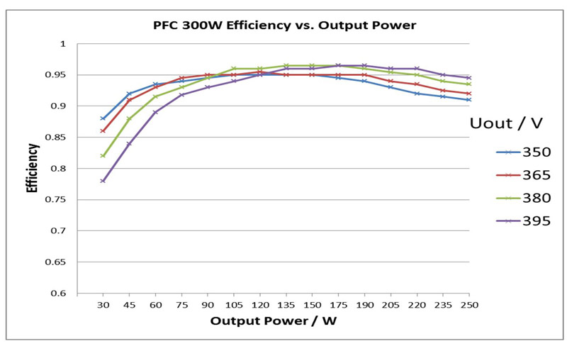
The efficiency behavior of a PFC-boost converter was performed on one 300W system utilizing digital controller ADP1047 [8]. By keeping constant input voltage 230Vrms and constant output voltage UOUT in steps 350V, 365V, 380V, 395V, the power efficiency for different output power level was measured. The results are presented in Figure 2.
Click image to enlarge
Fig. 2: Efficiency of 300W PFC boost converter [8] for different output power and output voltage levels
The power efficiency is a function of output voltage, as seen in the Figure 2. For the output power in range from 5% up to 30% of nominal output power is valid: the lower output voltage, the higher the converter efficiency. This is because switching loses become dominant for low output current. For higher output power level, the efficiency becomes higher when Uout increases. This is because conductor losses become dominant by high output current level.
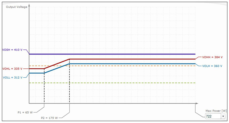
So, for some particular power level intervals, monotone function efficiency versus output voltage can be assumed. Power efficiency improvement can be achieved by changing output voltage when output power changes. The digital power controllers ADP1047/48 allow easy implementation of a linear function UOUT for varies output power level. Figure 3 shows an example of the linear output voltage change versus output power. The so-called “Smart Voltage” function can be programed by means of guided user interface.
Click image to enlarge
Fig.3 New adaptive bus voltage mode allows linear voltage change in respect to two output power levels P1 and P2
Power losses analysis for DC/DC converters
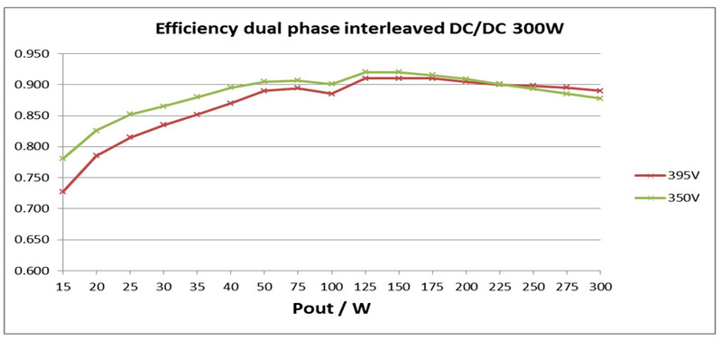
DC/DC converter efficiency behavior was analyzed for different input voltage level in order to find the optimum system efficiency. One dual phase interleaved 300W converter with Uin range 350V~400V and with Uout=12V has been analyzed [7]. This DC/DC using digital power controller ADP1046 was equipped with dynamic phase shedding, which allows phase disabling at low output power range. The power efficiency behavior versus output power for different Uin values was measured.
The converter works at light load with higher efficiency, when Uin is lower than nominal value. At high output power, the efficiency increases as Uin increases. This behavior is similar to the efficiency behavior of PFC converter from subchapter 3.1. Figure 4 demonstrates power efficiency behavior of DC/DC converter. Some efficiency gain at weak load can be achieved by using phase shedding mode. One phase was disabled at output power range below 100W. It can be seen additional efficiency gain below 100W output power.
Click image to enlarge
Fig.4. Power efficiency of DC/DC converter for two different input voltage 350V and 395V
Dynamic control of intermediate bus voltage
Earlier the power efficiency behavior of PFC and of DC/DC converters for different UIBV has been analyzed. In general, power efficiencies of both converters become higher at low output power range when the UIBV becomes lower. The power efficiencies become higher at nominal output power range when the UIBV becomes higher. This means, it exists an optimum UIBV offering the maximum system efficiency for particular output load. Thus, dynamically control of UIBV versus output power can be applied to increase system efficiency. One method providing dynamically control UIBV can be realized by remote control by means of serial control bus, as suggested in Fig.1. One master controller and galvanic isolation between PFC- and DC/DC serial bus nodes are needed.
To overcome those disadvantages and to simplify the control law of optimum system efficiency one new algorithms can be used. The input power level value can be taken for dynamically control of UIBV instead of output power level. Some digital power controllers have the ability to measure input power level, as this function is requested for telemetry and for protection measures.
The digital power controller ADP1047 is equipped with dedicated circuit allowing accurate measurement input power and with a control circuit allowing dynamically adoption of UIBV. It is simple to program the gain and power thresholds for the dynamically UIBV control. Figure 3 presents how to adjust the power thresholds and output voltage level in guided user interface (GUI) of ADP1047. This setup shows linear function UIBV for input power level between 65W and 175W.
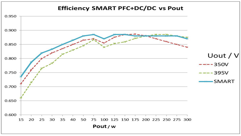
Those power thresholds were adjusted as result of power efficiencies analysis PFC-and DC/DC-converter. Above input power value 65W, UIBV increases linear allowing the system to work by optimum power efficiency. Above power level 175W, UIBV remains at 395V providing higher efficiency at high UIBV and high output power level. The system efficiency plot for two constant values UIBV and one dynamically controlled UIBV is presented in Figure 5. The red line represents system efficiency for constant UIBV =350V, where the green line for UIBV =395V.
Click image to enlarge
Fig.5. System power efficiency comparison for constant IBV of 350V (red trace), of 395V (green trace) and for dynamically adopted IBV by means of SMART-algorithms (blue trace)
The blue line represents the system efficiency, when dynamically control UIBV (SMART-Voltage mode) is enabled for system parameters presented in Fig.3. The sense of SMART-Voltage mode is to adjust the power thresholds at the points allowing achieving the upper efficiency-envelope lines in Fig.2 and Fig.4 for minimum and for maximum UIBV values. The minimum- and maximum UIBV values are determinate by the PFC- and by DC/DC dimensioning. The efficiency cross-points for minimum and maximum of output voltages (PFC) as well as of input voltage (DC/DC) determine the power thresholds of the SMART-mode function.
An adaptable process
A new method offering dynamically adjusting of intermediate bus voltage in power supply system consisting of PFC- and DC/DC converter has been presented. The method can be adapted for autonomous efficiency optimization. The PFC controller adjusts the output voltage for wide input power range in order to achieve the best efficiency for particular output load value. The dynamically adjusting takes into account the efficiency behavior of PFC- and of DC/DC stage. The results show efficiency improvement in range of 2…3 % for whole output power range. The SMART-function, implemented into digital PFC controller allows self-tuned, adaptive change of the intermediate voltage for optimum system power efficiency in wide load range.
References:
[1] www.80plus.org/
[3] www.climatesaverscomputing.org/
[4] J. Hwang and A. Chee, “Improving efficiency of a pre-/post-switching
regulator (PFC/PWM) at light loads using green-mode function,” IEEE
APEC Proc., pp. 669-675, 15-19 Feb 1998
[5] D. M. Van de Sype, K. De Gusseme, A. P. Van de Bossche, and J. A.
Melkebeek, “Input current distortion of CCM boost PFC converters
operated in DCM,” IEEE Trans. Ind. Electron., vol. 54, no. 2, pp.
855-865, Apr. 2007
[6] N. Schoenitz „Optimising power consumption of embedded systems using smart power supply solutions“, 4. Elektronik Digital Power Congress 2013, Munich, www.digital-power-congress.de/
[7] www.analog.com/static/imported-files/user_guides/UG-589.pdf
[8] www.analog.com/static/imported-files/pwr_mgmt/DigitalPower/PRD1334_ADP1047_EVAL_Rev1-0720.pdf