Testing, characterization and evaluation of PV inverters
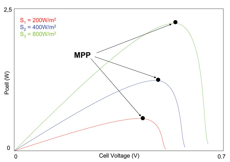
Figure 1: Power-Voltage Curve of a photovoltaic cell for differing light levels
In the utilization of solar panels, maximum power point tracking (MPPT) is the automatic adjustment of electrical load to achieve the greatest possible power harvest, during dynamic variations of light level, shading, temperature, and photovoltaic module characteristics. Photovoltaic (PV) panels generate current / voltage with a highly variable behaviour due to the fluctuations in energy flow from the sun. The typical behaviour of the power generated by a panel for varying levels of sunlight is outlined in Figure 1. For each level of radiation, there is a point at which the panel gives the Maximum Power Point, or MPP. MPPT technology To take full advantage of the energy generated from the panel, or photovoltaic field, it is necessary that the control interface continually tracks the MPP. The electronic circuit that performs this function is known as the Maximum Power Point Tracker (MPPT). The combination of using MPPT technology with modern photovoltaic inverters enables panel manufacturers to offer considerable performance improvements of the PV energy generation facility. Looking again to Figure 1, we see the working curve of a generic solar cell, and from that we can adapt the MPPT inverter systems to work with the entire PV array, to remain as close as possible to the MPP. There are two kinds of MPPT technology: analogue and digital. Both can be expressed as a transfer function (FDT) either an algorithm embedded within a microprocessor or a mathematical function that describes the operation of a complex system that consists of several components.

Simulation of a Photovoltaic field To prove this technology and its ability to cope with the unexpected - such as rapid changes in solar intensity caused by a passing cloud - a series of tests can be carried out to simulate this by varying the voltage and current inputs to the MPPT inverter. This is because the solar panel's electrical parameters are voltage and current, both of which are dependent on the light intensity hitting the photovoltaic cell; the worse the lighting level, the lower the output voltage and current. Simulating the actual behaviour of a photovoltaic field is very important; it enables the OEM to optimise the FDT MPPT inverter improving internal performance and efficiency. In Figure 2, the black line illustrates how close the MPPT technology tracks to the MPP, during a slow change in light intensity, while the red trace shows the loss of control when change in light intensity are too fast - under these circumstances, the use of MPPT technology is inappropriate.
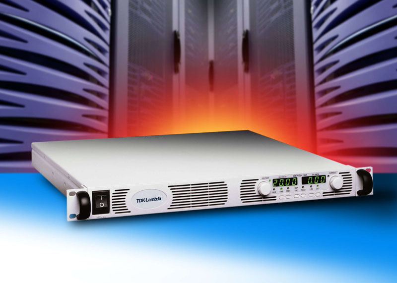
An efficient choice In order to simulate these events, programmable (laboratory) power supplies, such as the Genesys™ range from TDK-Lambda, are highly effective. With power ratings from 750W to 60kW and outputs of up to 600V, the Genesys™ series feature digital interfaces (RS232-485 and LAN interfaces.); these enable the simulation engineer to set the six pairs of VI parameters of the solar system to simulate the certain operating conditions of the photovoltaic field. Using a sequence of several VI pairs allows the engineer to reconstruct a curve and the simulation parameters in order to see how the inverter operates. The digital interfaces of the Genesys™ power supply also enable the engineer to read the output voltage and current being absorbed, allowing the R&D team to create an automatic test report. To simulate the extreme conditions - such as quick changes, drops and overshoots - FAST and PSINK options are available to the Genesys™ to respectively improve the response time to a few milliseconds and integrated active loading so that very complex simulation can be created. How to measure the efficiency of a photovoltaic inverter The efficiency of an inverter is the ratio between the AC and DC power consumption: ? = PAC / PDC But in the case of inverters for photovoltaic applications, which must work with extremely variable power inputs and weather conditions that may differ from region to region, the below definition is closer to actual conditions. In the particular case of Europe, the efficiency of an inverter is defined as follows: ? EURO = 0.03 • ?5% + 0.06 • ?10% + 0.13 • ?20% + 0.1 • ?30% + 0.48 • ?50% + 0.2 • ?100% Where: ?xx% is the inverter's efficiency when the input power is xx% of maximum power handling capacity. The result is an average efficiency that closely reflects the different conditions of radiation, and then input power, according to a weighted contribution regarded as representing the average distribution of sunshine levels recorded throughout Europe. www.uk.tdk-lambda.com