Device considerations for backlight boost conversion purposes
Portable electronics devices (such as smartphones) are having more and more functionality squeezed into them all the time. Simultaneously, there are exacting pressures being placed upon engineers to lengthen the period these devices can last between battery recharges and bring device models to market with sleeker form factors.
Constituent components need to get smaller, and system power losses need to be reduced. One major source of power loss comes through the use of boost converters to drive display backlights. Specifying the Schottky diode element is therefore critical. Let’s look in detail at the different steps that should be taken during the selection process.
The boost converters utilized in LED backlighting for modern portable electronic device designs have a tendency to consume a sizeable amount of power, normally representing the largest proportion of the device’s overall power budget and draining the battery. Their operation therefore needs to be as efficient as possible.
The Schottky diode
The Schottky diode is an integral part of backlight boost converter implementation. Inclusion of a suitable Schottky diode will have a major influence on maintaining elevated boost converter efficiencies. The consequences of this are that the time period between battery recharges can be extended and a more expansive feature set can be incorporated into the system design.
Prior to embarking on Schottky diode specification and sourcing, it is important to have a good grasp of the boost converter mechanism itself. Backlights generally utilize White LED emitters. These have a forward voltage that will typically be between 3.0V and 3.6V. Generally speaking, portable electronic devices rely on single-cell Li-I batteries with an operating range of between 2.5V and 4.2V. As the voltage of a Li battery reduces toward 2.5V there is no longer sufficient voltage for driving the LEDs directly. This is where the boost converter comes in.
The Li battery’s voltage serves as the input voltage of the boost converter. The output voltage value will be derived from the forward voltage required to drive the LEDs which form the backlight, and the configuration into which these LEDs have been arranged. Some system designs will employ a one string arrangement, while others will require two strings. Given that the LEDs’ forward voltage (as already stated) will be around 3.0V to 3.6V, this will lead to an output voltage of 18V to 36V.
Duty cycle
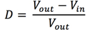
A boost converter’s duty cycle (D) can be determined using the somewhat idealized equation shown below (see Equation 1). Typically boost converter duty cycles will be within the region of 80% to 90%. This means that the MOSFET will be switched on for around 90% of the cycle so that the inductor’s magnetic field can be charged.
While the MOSFET is on, the Schottky diode is reversed biased (with the output voltage across its cathode to anode). When the MOSFET is turned off, the energy that has built up on the inductor is subsequently discharged through the Schottky diode into the output capacitor, and in turn into the LED string (or strings).
The charge received by the output capacitor during this phase of the cycle is adequate to supply the LEDs with a constant current when the MOSFET turns back on to begin the next cycle. A precision resistor can be added to the system (placed in series with the LED string) - allowing the gaging of a very small voltage through which feedback can be supplied to the controller.
Boost-converter currents
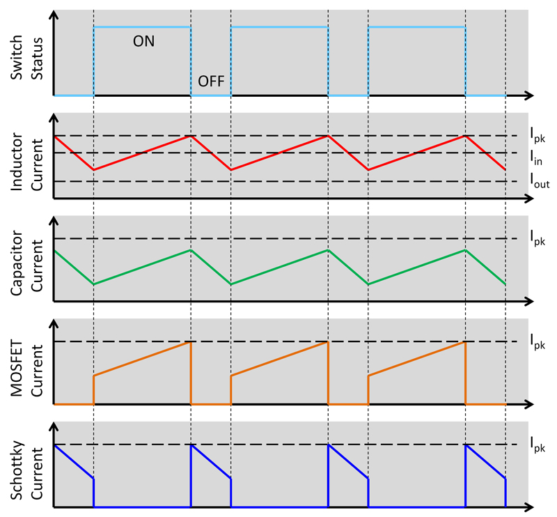
Being aware of the different currents present within the boost converter will be of value when looking to specify a Schottky diode for your backlighting system. Details of these currents are illustrated in Figure 1.
Click image to enlarge
Figure 1. Boost Converter Currents
They are as follows:
The average input current (IIN(avg)) - Which is also the average current of the Schottky diode when it is forward biased.
The peak inductor current (IPK) - This is the current that the Schottky diode will be subjected to when the MOSFET is switched off. Its value will linearly subside as the magnetic field of the inductor weakens in strength until the MOSFET turns back on to begin the next cycle.
The output current (IOUT) - This is set by the controller that has been incorporated into the system. For LED backlights the output current is normally somewhere between 15mA and 25mA for each LED string.
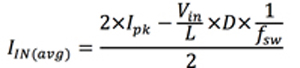
The boost converter’s IPK can be calculated via use of Equation 2, while the value of IIN(avg) can be determined using Equation 3.

Key parameters effecting Schottky diode selection
There are numerous parameters that need to be taken into account when specifying a Schottky diode for your backlighting system. Among the most important are:
Forward current rating (IF) - This is the maximum DC current that the device is capable of accepting. It relates directly to the values of IPK and IIN(avg). IF should be greater than IIN(avg) to be fully effective.
Reverse voltage (VR) - Which is defined as the maximum voltage that can be applied across the diode when it is reversed biased. If boost converter implementation is being discussed, this voltage will equate to the output voltage of the converter. It is recommended that the boost converter’s controller element should have a built-in over-voltage protection (OVP) mechanism, in order to ensure that operational failure through voltage surges or spikes can be avoided. The Schottky diode’s VR should then be as close to the OVP threshold as possible, in order to maximize operational efficiency.
Forward surge current rating (IFSM) - This is the maximum current that the diode can withstand during a voltage surge condition when it is in the form of a single pulse.
Repetitive peak forward current (IFRM) - Likewise, this is the maximum currents that can be withstood when exposed to continuous pulses. The IFRM rating for a Schottky diode will be lower than its IFSM rating.
Reverse leakage current (IR) and forward voltage (VF) - These two parameters should be looked into in tandem rather than separately. In the past it was viewed that the lower boost converter’s VF was the better Schottky diode performance would be.
Unfortunately, it is no longer quite that simple, as the progression of semiconductor process technologies has meant that using lower VF devices can now result in compromises being made due to comparatively high leakage currents. In the context of LED backlighting for portable electronics devices, an application where the output/input voltage ratio is characteristically high, such leakage currents are going to be a problem.
Since the Schottky diode will be reversed biased for most of the time, the leakage current will have a substantial impact on the diode’s power dissipation. Just picking the diode with the lowest VF will therefore not be enough. A more advisable approach is to combine the IR and VF parameters together and then assess how both will contribute to the diode’s overall power dissipation - thus ensuring that it is optimized for the proposed boost converter implementation. Equations 4 and 5 can be used to accomplish this.
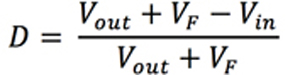

D = Boost Converter’s Duty Cycle PD = Power Dissipation of Diode
Vout = Boost Converter’s Output Voltage Vin = Boost Converter’s Input Voltage
IR = Diode’s Reverse Leakage Current at Vout IF = Average Forward Current through Diode
VF = Forward Voltage of Diode at IF
Component packaging
With regard to the packaging of the Schottky diode, thought must be given to both the package size and the package style. The thermal management aspect is of great importance to boost converter implementation - especially as portable electronics designs become more space constrained (with more components being packed into ever smaller enclosures). By keeping the diode’s junction temperature in check the operational lifespan of this device can be extended.
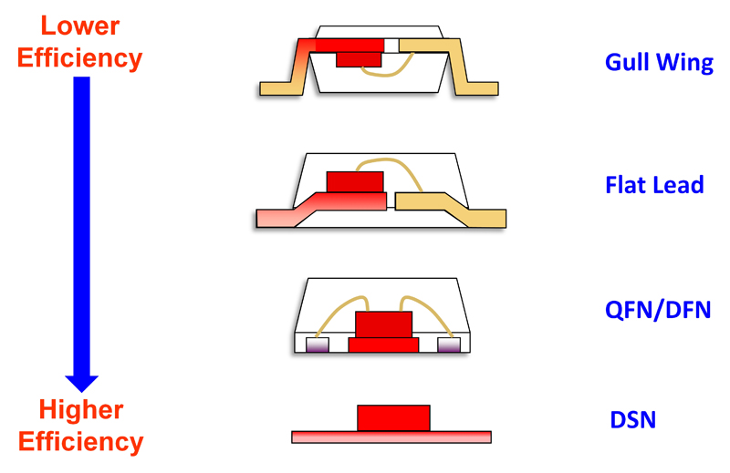
With little or no room for heatsinking, choosing a package format with a high thermal conductivity and a short thermal path from the die to the PCB that will allow heat to be dissipated proficiently will therefore be extremely beneficial. Details of the different package styles available and their respective thermal efficiencies are shown in Figure 2.
Click image to enlarge
Figure 2: Thermal Efficiency Improvements Made Possible by Advances in Packaging Technology
The gradual migration from quad flat no-lead (QFN) to discrete flat no-lead (DFN) and then to dual silicon no-lead (DSN) package types has allowed a steady improvement in thermal efficiency levels to be realized. The particularly high thermal efficiency furnished by DSN is a result of the shortened thermal path between the die and the PCB onto which the diode has been mounted. By eliminating a leadframe, the thermal resistivity is lowered significantly.
Regarding package size, board space constraints mean that engineers are procuring power ICs and discretes with smaller packages. These in turn calls for smaller dies. For Schottky diodes, the smaller the die is the higher the VF, will be - as this relates directly to the Schottky contact area.
As the die size becomes smaller the leakage current decreases. Using the power dissipation calculation outlined in Equations 4 and 5 engineers can get visibility of the various tradeoffs that moving to smaller packages will entail. It is not advisable to select a Schottky diode primarily on its package size. The maximum acceptable package size should be known, but all package formats smaller than this should ideally be contemplated and their feasibility checked.
In conclusion, appropriate selection of a Schottky diode is fundamental to LED backlight boost converter construction. There are a multitude of different factors that need to be considered, but if the correct component is specified, the battery life of portable electronic devices can be prolonged. By liaising with a diode manufacturer who offers a broad product portfolio it will be possible to find the one that exactly fits your specific requirements, without having to make unnecessary compromises.