Addressing the design challenges of stepper motor applications
Combining ultra-precise control with long operating life, stepper motors have become a critical building block in motion-based applications ranging from white goods to factory automation and robotics to printers and point-of-sale equipment. For the designer, the challenge is to ensure the best combination of performance, functionality and robustness while addressing key functional safety considerations.
At the same time, keeping heat dissipation to a minimum demands optimized efficiency. Addressing these challenges requires careful design of motor drive circuitry. In particular, choice of motor driver ICs and support tools is critical to both application success and speed of development.
A growing market
Research firm, P&S Market research, predicts that the global stepper motor market will grow from an estimated $1,654.1 million in 2015 to $2,172.5 million in 2022 – showing a CAGR of approximately 3.8%. Target applications for these motors include industrial CNC machines, 3D printing, point-of-sale systems, valve control, office equipment, factory automation and robotics. And as these applications become smaller and more integrated, the growth of the market for miniature stepper motors is also expected to increase.
In addition, hybrid stepper motors are increasingly being used, particularly in surgical hand tools, pumps and ventilation equipment and this sector is expected to continue to grow along with the packaging sector where stepper motors are heavily used in the integrated machines that offer greater productivity, reliability and efficiency – with reduced costs.
At their simplest level, stepper motors are a special class of brushless DC motors that can be operated via digital control in an open loop configuration without feedback from sensors or encoders. These motors have a different construction to ordinary DC motors. In a simple DC motor, the permanent magnet (stator) is on the outside and the coil (rotor) is on the inside. This is reversed in a stepper motor where the coil (stator) is on the outside and permanent magnets form the rotor.
Key advantages of stepper motors include:
- Availability of full torque from standstill
- Precise and repeatable positioning (good stepper motors have an accuracy of 3% - 5% per step and this error is non-cumulative from one step to the next)
- Excellent start/stop/reverse response
- Reliability (as there are no contact brushes)
Important application considerations
While stepper motors are theoretically easy to control, there are still a number of important considerations for the application designer. Take, for example, speed of motor rotation. With DC motors, speed increases as the applied voltage increases. Stepper motors are “digital” – increasing the voltage level has no effect on rotation speed. The speed of a stepper motor is controlled by the pulse timing – the higher the rate, the faster the motor turns.
However, every motor has a maximum acceptable pulse rate. This, combined with the number of pulses per full turn, determines the maximum possible speed of rotation. The impact of possible reduction in torque at higher rotation speeds (as a result of winding inductance) and ‘motion quality’ – i.e. vibration – must also be taken into account.
The precision and accuracy demanded by the target application is also important. For those applications that require very high levels of accuracy, for example, control schemes will be expected to support advanced techniques such as micro-stepping, where fractional currents are applied. At the same time, designers must understand how the stepper motors have to accelerate and decelerate in order to achieve optimum performance.
As stepper motor drive schemes are essentially a special application of power management techniques, consideration needs to be given to the efficiency and safety of the system. In industrial and other electrical noisy environments, for instance, high levels of ESD resistance will be needed for application ‘robustness’. Designers may also need to incorporate circuit protection features such as over current protection (OCP) and current limitation, under- and over-voltage lockout (UVLO/OVLO), and thermal shutdown (TSD).
Integrated stepper-motor drivers
In recent years the advent of integrated stepper motor driver (SMD) ICs has helped designers to simplify the implementation of stepper motor control schemes while saving board space and reducing component count. Increasingly these ICs are being made available with development boards and reference designs to build comprehensive ‘support eco-systems’ that further speed the evaluation and prototyping of stepper motor applications.
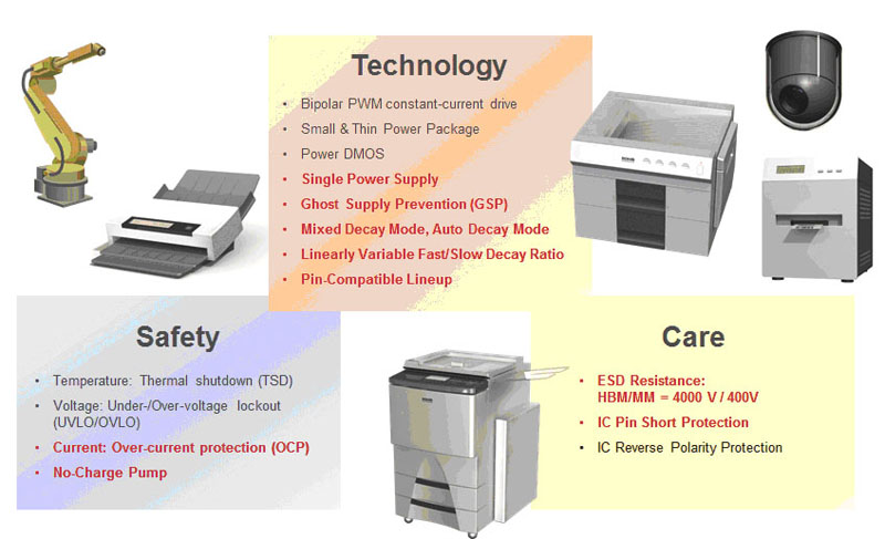
For example, Rohm’s family of integrated SMDs provides a good illustration of some of the latest developments in this area. Available with a wide range of supply voltages and current capabilities, these advanced devices have been developed using knowledge and experience gained over many years of developing power management solutions. Specifically, ROHMs SMD design philosophy is based on addressing the three fundamental areas of technology, safety and robustness, as illustrated in Figure 1.
Click image to enlarge
Figure 1: Latest SMDs combine high levels of integrated technology with safety and robustness features
The ROHM SMD family for bipolar stepper motors includes 45V high-voltage, 36V standard, micro-step and DC, and low-voltage (15V) drivers with both CLK-IN and PARA-IN variants. Each device uses the company’s established high-density, mixed-signal bipolar+CMOS+DMOS (BCD) semiconductor process technology. This provides the means for integrating highly efficient DMOS power technology with lower power control circuitry and requisite protection functionality in a single device. The integration of a P-channel power device, simplifies the power output stages as the charge pump that would normally be used to drive the high side n-channel is not needed. This, in turn, ensures a more robust and reliable design.
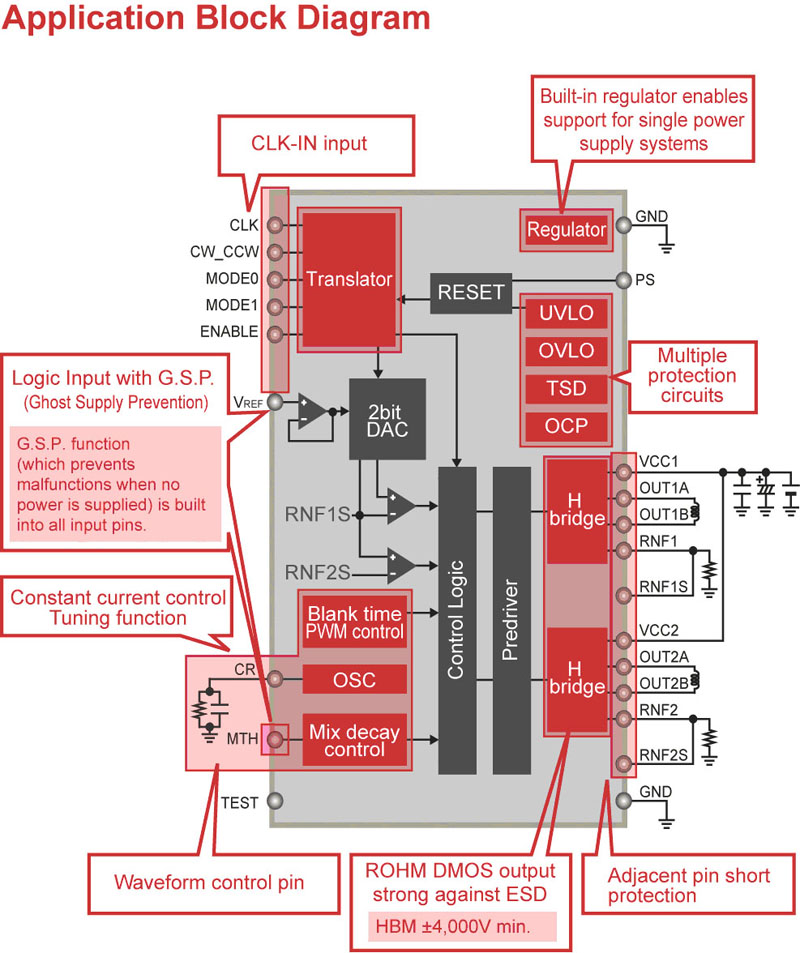
As an example, Figure 2 shows a schematic of one of a new ROHM solution that will be launched shortly. This high-performance, high-reliability 36V SMD is available with current ratings of 1.0A (BD63710EFV), 1.5A (BD63715EFV), 2.0A (BD63720EFV) and 3.0A (BD63730EFV) and is supplied in a compact 28-pin HTSSOP package.
Click image to enlarge
Figure 2: Integrated 36V SMD
Each device incorporates a constant current PWM driver for optimized efficiency and a single, integrated power supply that eliminates the need for external power supplies and associated passive components. This built-in power supply saves space and reduces component count when compared to discrete alternatives as well as delivering enhanced EMI performance.
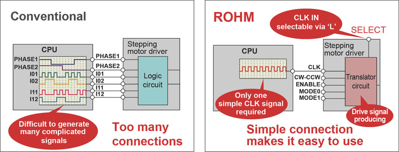
High levels of integrated functionality offer simplicity for the designer. As an example, many SMDs require a multi-phase signal from a CPU to control the motor. Using ROHM’s innovative CLK-IN feature, the CPU only needs to provide a single-phase clock signal - all of the low-level phasing is addressed with the on-board translator circuit (see Figure 3).
Click image to enlarge
Figure 3: Integrated drive signal translation simplifies the implementation of stepper motor control
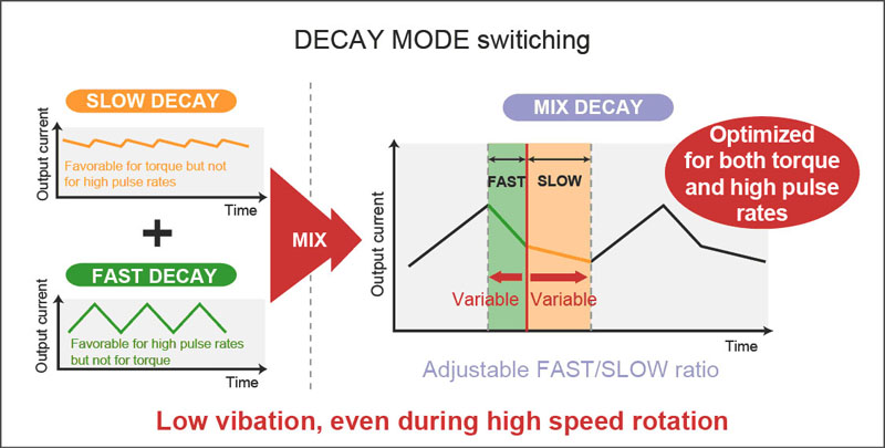
Typically, when driving a stepper motor, a slow decay in drive current is desirable for smooth torque and low vibration, whereas a fast decay is required for high-speed operation with high pulse rates. As Figure 4 shows, ROHM’s SMDs incorporate a sophisticated mixed decay capability that allows the decay rate to be optimized based on the motor’s characteristics and application requirements. Using mixed-decay mode designers can fine-tune motor performance to address issues associated with vibration and current waveform distortion.
Click image to enlarge
Figure 4: Decay mode switching
As Figure 2 shows, high levels of protection are provided in the form of built-in UVLO, OVLO, TSD and OCP functionality. The SMDs also incorporate a proprietary ‘Ghost Supply Prevention’ function on all input pins that prevents spurious voltages causing the stepper motor to move in an uncontrolled way when the SMD is unpowered. At the same time, the H-bridge DMOS output ensures a minimum human body model (HBM) ESD resistance of ± 4000V.
Design Support - Arduino Evaluation Kit
Selecting advanced and highly integrated devices is only part of the solution. Today’s design engineers are under ever-increasing pressure to deliver right-first-time designs in ever-shorter timescales. As a result, the nature of the ‘support eco-system’ available from the SMD manufacturer is becoming an increasingly important aspect of supplier selection.
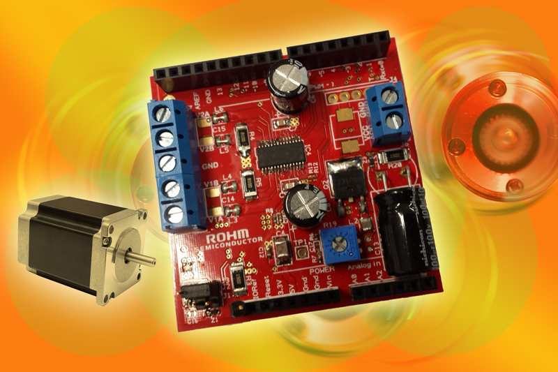
To support design-in and evaluation of its own SMDs, ROHM is going to launch an Arduino-based evaluation kit (EVK). Designed as a ‘shield’ to plug directly into the Arduino main board, this EVK, which is shown in Figure 5, allows engineers to rapidly evaluate and prototype stepper motor systems.
Click image to enlarge
Figure 5: The ROHM Arduino-based EVK allows rapid evaluation and prototyping of stepper motor systems
The EVK will be available in 15 different model variants – each based on a particular ROHM SMD IC. This comprehensive solution covers supply voltages from 8V to 42V, allows up to 2.5A / phase, and supports micro-stepping and single- or multi-phase control of one or two stepper motors. The ‘easy to adapt’ EVK is supplied with a software library and example programs to facilitate a rapid learning curve.
Once the design is proven, engineers can move rapidly from prototype to production phases fully supported by the Bill-of-Materials (BOM) and Gerber-based PCB layouts that are provided with the EVK.