Capability of wire-bonded power diodes
Figure 1: I-V characteristics of 10ms half sine pulses at different peak currents. Curve (c) is slightly above, curve (d) is far above the destruction threshold.
The ability of silicon power diodes to withstand a rapid forward current load, described by its i2t-value, is an important criterion that has to be regarded in the selection of the proper devices for power electronic applications. The dependence of the surge current limit on its pulse width is investigated for different diode types. A simple analytical formula for the maximum achievable surge current is derived. Historically, diodes have been employed in passive input rectifier circuits prior to their extensive use as free wheeling diodes (FWD) for inverters. In rectifier circuits the time dependence of on-state current is closely linked to the frequency of the supply voltage. Therefore 10ms sinusoidal half wave pulses are typically applied to characterise the surge current capability. But there are working conditions that demand other pulse durations like in the 16? Hz power line of railway supplies where tP=30ms occur at the input rectifier. Furthermore a rectifying action of the FWDs may also happen if energy is regenerated from the motor through the inverter into the DC link capacity at frequencies below 50Hz giving rise to tP~100ms. On the other hand short but high current pulses have to be withstood by the diodes if the energy in the DC link capacitor discharges during a bridge short circuit. The circuit consisting of the stray inductances and the capacitance of the inverter gives rise to damped current oscillations characterised by pulse widths far below 1ms. Surge current experiments The surge current is measured via half-sine-current of a certain pulse length tP. Mostly, tP=10ms from a transferred 50Hz line is used. Fig. 1 and 2 show typical I-V characteristics taken for a succession of pulses.
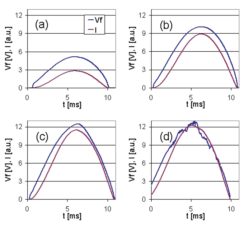
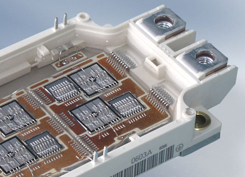
The curves depict I-V curves which are typical for diodes both in the up- and downward branch of the sinusoidal current. In fig. 2 the time dependencies of current and forward voltage drop are shown. The failure signature of a FWD destroyed by a surge current overload is designated by molten areas are located around the bond wedges. The failure signature indicates a thermal limitation of the surge current capability by local over-heating and destruction of the aluminium metallization layer. Interdiffusion of silicon and aluminium occurs at the die surface leading to a spiking of aluminium. The destruction of the upper pn junction is a consequence. Therefore, a loss of the blocking capability is the most sensitive indicator to determine the destruction threshold during surge current experiments.
Analytical approach to the thermal limitations of surge currents The temperature swing at the die surface is given by the thermal impedance Zth and the applied power:
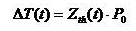
with a step function (1)
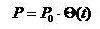
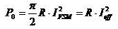
The pulse power of a sinusoidal current is now approximated as an effective square pulse with a temperature independent resistance R: (2)
Assuming equal destruction temperatures, eqn. (1) and (3) result in a simple formula for the dependence of the peak current IFSM at an arbitrary pulse duration tp: (3)
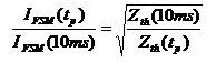
The peak current of a pulse depends only on the square root of the ratio of its thermal impedance value with respect to a reference pulse. Fig. 3 shows the experimental data normalized to the 10ms values together with a scaling curve according to eqn. (4). The datasets for all diodes scale onto one single curve. Thus, the surge current of all diodes is supposed to be limited by the same physical mechanism. The thermal impedance curve is determined via a finite element approach under the assumption of a homogeneous power loss in the diode volume because of the lack of reliable experimental Zth-data for such short time scales. (4)
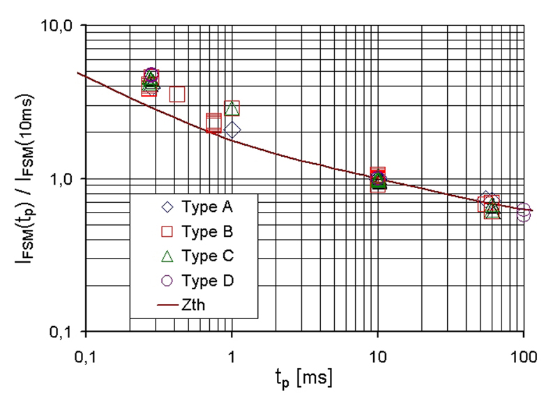
There is a deviation between the experimental data and the thermal impedance considerations at short times. This is mainly due to the dynamics of the spike formation itself. Temperature alone is not sufficient since the pulse time and thus the diffusion time is also of importance. Therefore, the thermal impedance scaling, which is based only on the temperature argument, underestimates the actual surge current limit for short pulse durations because there is not enough time for sufficient spiking.
Simulation results Finite element simulations of a test diode with one bond wedge were carried out to clarify the failure mechanism. Fig. 4 shows snapshots taken at different times during a simulation run for IFSM=172A and tp=10ms. The areas in the vicinity of the bond wedge get hottest during the sinusoidal current pulse. This corresponds very well to the failure signature, where molten aluminum is located around the wedge.

A comparison of the diode temperature distribution for different pulse durations is shown in fig. 5. For long pulses (here 100ms) the whole wedge area is heated. The bond wire itself is the hottest part. This is not surprising as one comes closer to the DC limits. Pulses with tp<100ms are limited by the temperature swing of the diode's metallization. For shorter pulse widths a localization of hot spots near the wedge can be observed. Assuming that the failure events can be described by an equal maximum temperature of the hot spots, the dependence of the maximum surge current on the pulse width can be derived from a finite element calculation. The result is given in fig. 6 together with the prediction expected from the thermal impedance model of eqn. (4).
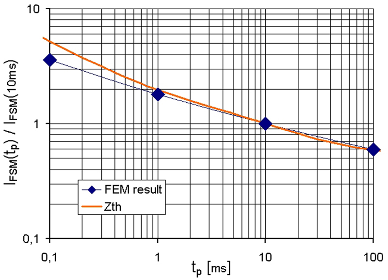
The simulation result resembles the scaled thermal impedance data for pulse durations of tp>5ms. The thermal impedance used here is computed for a specific test assembly. The deviations for small pulse widths can be explained by the high local temperature gradients which are in the order of the finite element mesh size. Improving the finite element mesh near the wedge would enhance the match of the results. Conclusions The surge current limitations of wire bonded silicon free-wheeling diodes were studied both experimentally and numerically. An analytical formula describing the peak current IFSM limit for different pulse widths based on the thermal impedance is derived. It is useable for the determination of a lower bound for the actual IFSM. Finite element simulations are used for the study of the destruction mode. The temperature distribution found numerically corresponds to the experimentally gathered failure signatures. www.infineon.com


