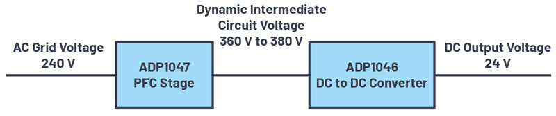
Switched Capacitor Converter for High-Power Applications
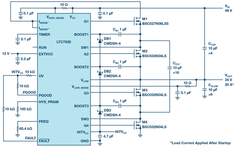
Figure 1. A 48 V to 24 V/20 A voltage divider with a power density of 4000 W/in3
The power density of a dc-to-dc converter is generally limited by bulky magnetic components, especially in applications where the input and output voltages are relatively high. Inductor/transformer size can be reduced by increasing the switching frequency, but this reduces converter efficiency because of switching-related losses. It is better to eliminate the magnetics altogether with an inductorless switched capacitor converter (charge pump) topology. Charge pumps can increase power density as much as 10× over a conventional converter without sacrificing efficiency. Instead of an inductor, a flying capacitor stores and transfers theenergyfrominputtooutput.Despitetheadvantagesofchargepump designs, switched capacitor converters are traditionally limited to low power applications, due to the challenges presented in startup, protection, gate drive, and regulation.
The LTC7820 is a fixed-ratio, high-voltage, high-power switched capacitor controller that yields small and cost-effective solutions for high-power, non-isolated intermediate bus applications with fault protection. The LTC7820’s features include:
- Low profile, high power density, capable of 500 W+
- VIN max for voltage divider (2:1): 72 V
- VIN max for voltage doubler (1:2)/inverter (1:1): 36 V
- Wide bias VCC range: 6 V to 72 V
- Soft switching: 99% peak efficiency and low EMI
- Soft startup into steady state operation
- Input current sensing and overcurrent protection
- Integrated gate drivers
- Output short-circuit/OV/UV protection with programmable timer and retry
- Thermally enhanced 28-lead 4 mm × 5 mm QFN package
48 V to 24 V/20 A Voltage Divider with Power Density of 4000 W/In3
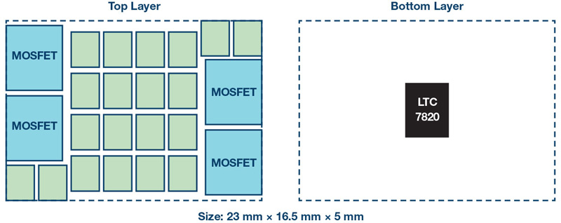
Figure 1 shows a 480W output voltage divider circuit featuring the LTC7820. The input voltage is 48 V and the output is 24 V at up to 20 A load. Sixteen 10 µF ceramic capacitors (1210 size) act as a flying capacitor to deliver the power. The approximate solution size is 23 mm × 16.5 mm × 5 mm as shown in Figure 2 and the power density is as high as 4000W/in3.
Click image to enlarge
Figure 2. Estimated solution size features 5 mm maximum height
High Efficiency
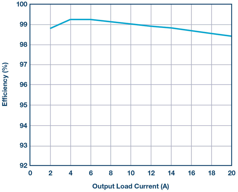
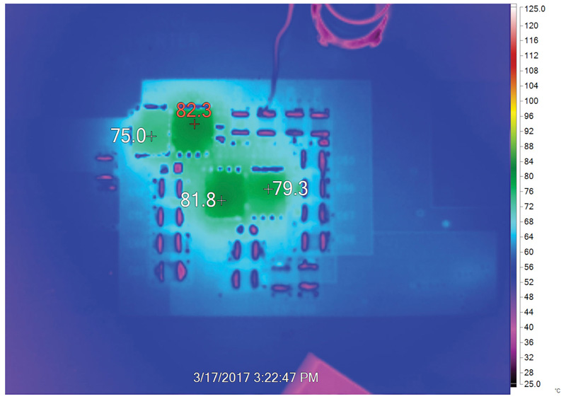
Since there is no inductor used in the circuit, all four MOSFETs are soft switched, greatly reducing switching-related losses. The converter can achieve high efficiency as shown in Figure 3, where the peak efficiency is 99.3% and the full load efficiency is 98.4%. The thermograph in Figure 4 shows a balanced thermal design with a hot spot temperature about 82.3°C in an ambient environment of 23°C and no forced airflow.
Click image to enlarge
Figure 3. Efficiency at 48 V input, 24 V output, and a 200 kHz switching frequency
Click image to enlarge
Figure 4. Thermal test at 48 V input, 24 V output at 20 A, and 200 kHz switching frequency
Prebalance Prevents Inrush Currents
In addition to impressive efficiency and thermal performance, the LTC7820 includes a proprietary prebalance method to minimize inrush current in voltage divider applications. The LTC7820 controller detects the VLOW_SENSE pin voltage before switching and compares it with the VHIGH_SENSE/2internally. If the voltage at the VLOW_SENSE pin is much lower than VHIGH_SENSE/2, a current source injects 93 mA of current at the VLOW pin to pull VLOW up. If the voltage at VLOW_SENSE is much higher than VHIGH_SENSE/2, another current source sinks 50 mA from VLOW to pull it down. If the voltage at VLOW_SENSE is near VHIGH_SENSE/2, that is, within the preprogrammed window, both current sources are disabled and the LTC7820 starts switching.
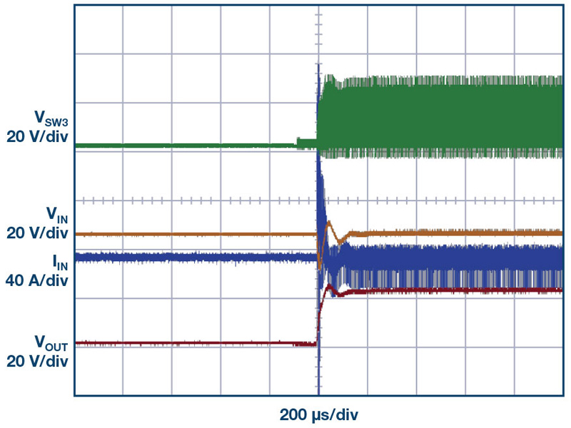
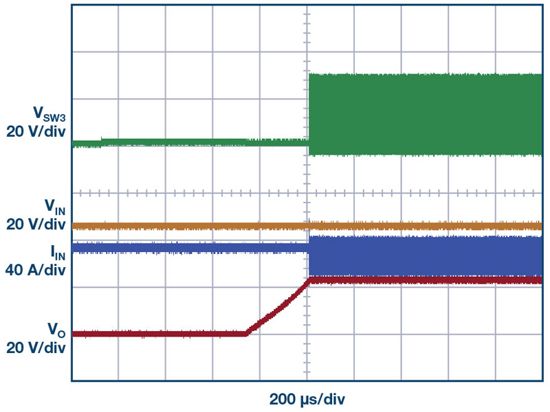
Figure 5 shows the enormous input inrush current that occurs at start-up without precharging—more than enough to damage the MOSFETs and capacitors. In contrast, no excessive inrush current is observed after the prebalance method is applied, as shown in Figure 6.
Click image to enlarge
Figure 5. Start-up waveform without prebalance shows large inrush current
Click image to enlarge
Figure 6. Startup waveform with LTC7820 prebalance shows elimination of inrush current
Tight Load Regulation
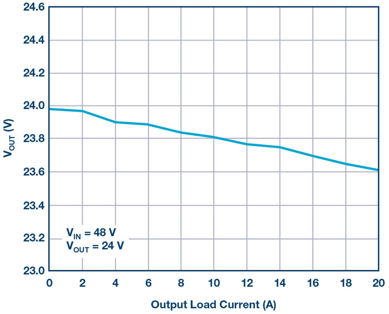
Even though the LTC7820-based voltage divider is an open-loop controlled converter, load regulation is tight due to its high efficiency. As shown in Figure 7, the output voltage drops only 1.7% at full load.
Click image to enlarge
Figure 7. Load regulation
Protection Features
The LTC7820 includes protection features to ensure high converter reliability. Overcurrent protection is enabled through a sensing resistor on the high voltage side. A precision rail-to-rail comparator monitors the differential voltage between the ISENSE+ pin and the ISENSE– pin, which are Kelvin connected to a sensing resistor. When the voltage at ISENSE+ is 50mV higher than the ISENSE–, an overcurrent fault is triggered, the FAULT pin is pulled down to ground, and the LTC7820 stops switching and starts retry mode based on the timer pin setup.
Further protection is available through the OV/UV window comparator. In normal operation, the voltage at VLOW_SENSE should approach half of VHIGH_SENSE. A window comparator monitors VLOW_SENSE and compares it to VHIGH_SENSE/2. The hysteresis window voltage can be programmed and is equal to the voltage at the HYS_PRGM pin. With a 100 kΩ resistor on theHYS_PRGM pin, the VHIGH_SENSE/2 voltage must be within a (VLOW_SENSE ±1 V) window during start-up and normal operation. Otherwise a fault is triggered and the LTC7820 stops switching.
Conclusion
The LTC7820 is a fixed ratio high voltage, high power switched capacitor controller that meets the power density demands of bus converters, high power distributed power systems, communications systems, and industrial applications. No inductors are needed.