Efficient approaches are needed at all points of the system
The “Energiewende” (energy transition) has resulted in a shift in thinking not only about the generation of electrical energy, but its distribution and consumption as well. Efficient approaches are needed for energy production and transfer on the one hand, and consumption on the other. What plays a role here is not only mere electric power dissipation, but also considerations such as low weight due to a compact converter design, lower cooling costs for electrical supply, or identical parts concepts based on a platform idea for reducing system cost.
For example, Infineon’s XHP platform, a new half-bridge module recently introduced during PCIM 2015, is the kind of device that can address the needs of future generations of converters. Such a half-bridge module enables the development of efficient converters that have been optimized for restricted installation spaces based on a platform concept.
As a result, the performance of the converter can be individually increased via a simple parallel connection to meet the requirements of the application, enabling the use of a half-bridge module in a wide range of applications. Examples of such include traction, energy transmission, renewable energy, and medium-voltage converters. Following is an explanation based on the example of converter topologies for medium-voltage drives (see Figure 1).

Click image to enlarge
Figure 1: The XHP highly-insulated half-bridge module from Infineon for voltages from 3.3 kV to 6.5 kV
Optimal control
Electrical drivetrains are used in a variety of applications. Modern power electronics make it possible to optimally control motors according to the load profile of the particular application area. The requirements for a given drive differ can greatly from the respective use. One important application area for high-performance, variable-speed electrical drives is in passenger and freight transport rail vehicles of all types. In this area, modern power electronics enable rapid and smooth starting and braking, and because of the electrical braking capability, at a high energy-efficiency with low mechanical wear and tear.
Due to various service requirements and the way infrastructure has grown historically, a variety of electrical systems exist in the area of traction: Local transport systems often work with a DC voltage of 750 V or 1500 V, which is supplied via a catenary or third rail. In long-distance transport, however, it is customary to deliver AC voltage of 15 kV to 25 kV or a DC voltage of 1.5 kV to 3 kV through an overhead line. The manufacturers of rail vehicles and traction equipment are therefore forced to offer a wide range of drive equipment in order to serve this diverse market effectively.
Since rail vehicles represent long-lasting investment goods, the demands on service life and electrical component reliability are high. It is also customary, however, to modernize older vehicles by replacing their electrical components. This is done not only to simplify the maintenance and upkeep, but also to achieve additional energy savings and improve passenger comfort. Such refurbishment projects demand a particularly high degree of flexibility from electrical equipment providers.
The area of electrical drives for industrial applications is also far from being uniform. Electrical drives for feed pumps, such as those used worldwide under a wide variety of operating conditions in the oil and gas industry, are subject to different requirements than stationary drives in steel mills. In the first case, it is essential to enable operation in a wide range of ambient temperatures and guarantee non-damaging transport from one operational site to the next even under adverse conditions. In the second, the important thing is high and easily predictable ruggedness to alternating loads to ensure years of trouble-free operation for such complex systems. What both scenarios have in common is the demand for a solution that is as efficient as possible. There is a special focus not only on the motor itself, but also the converter and the converter topology used.
Two-level topology
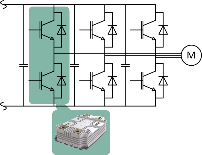
The classic two-level topology is the standard one for applications in the area of traction. It is also used in special industrial medium voltage converters such as mining converters for underground use (see Figure 2).
Click image to enlarge
Figure 2: Two-level topology with the half-bridge module XHP from Infineon
In traction applications where the catenary has a voltage of 1500 V, or where the intermediate circuit voltage ranges, for example, from 1800 V to 2200 V, it is customary to use a half-bridge that consists of at least two separate individual 3.3 kV switches. Depending on the required output, the parallel connection of several individual switches increases the nominal current. This requires a complex external circuitry for the modules.
A device such as the half-bridge module from Infineon significantly reduces this complexity, since an internal connection of the two individual switches to form a half-bridge and the separation of the load terminals into DC and AC greatly simplify the external busbars. On the DC side, the number of busbar layers is thus reduced to two. The optimized internal circuitry of the two switches also reduces the leakage inductances by about 50 percent. The connection of the switches to form a half-bridge in a single housing also has a positive effect on ohmic losses in the external busbars.
For the same output current and external busbar thickness, ohmic losses are only 75% of those in a typical single-switch solution. This is advantageous especially because the associated thermal losses cannot usually be diverted directly into a liquid cooling circuit, and are instead released into the interior air of the converter housing. In devices with a high protection class, the removal of this dissipated heat requires especially high system expenditures in the form of heat exchangers or even air-conditioning units.
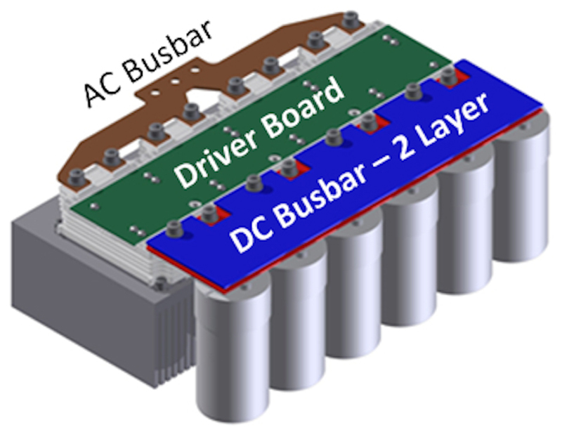
The Infineon half-bridge module also allows an increase in the nominal current by means of a parallel connection of the individual half-bridge modules. The scalable concept enables a finely graded equipment program that uses largely identical parts for all essential system components. The area on top of the module is intended for installation of the driver electronics and simplifies the parallel connection; it is designed to enable positioning in the tightest of spaces. This makes a compact converter design possible (see Figure 3).
Click image to enlarge
Figure 3: Air-cooled quadruple parallel connection with busbar and capacitor bank
Such a solution allows a compact, high-power-density construction of a half-bridge configuration for a phase leg with a two-level topology. Four additional aspects are particularly advantageous for traction applications:
- Half-bridge modules with a low nominal current are well-suited for vehicle concepts with individually controlled single axles.
- In general, the same modules can also be used for the auxiliary power converters.
- If energy storage units are to be used on the vehicle to improve recuperation, they can also be connected to the intermediate circuit through these half-bridge modules.
- The planned portfolio with different voltage classes in a uniform housing makes it possible to develop equipment for the different applications with a uniform converter design.
Multilevel topologies
In addition to the classic two-level topology, multilevel inverters are used in some applications. These topologies enable higher output voltages and a more precise adjustment of the AC output voltage to the sinusoidal shape. Only a fraction of the entire output voltage is supplied to the individual semiconductor switches [1].
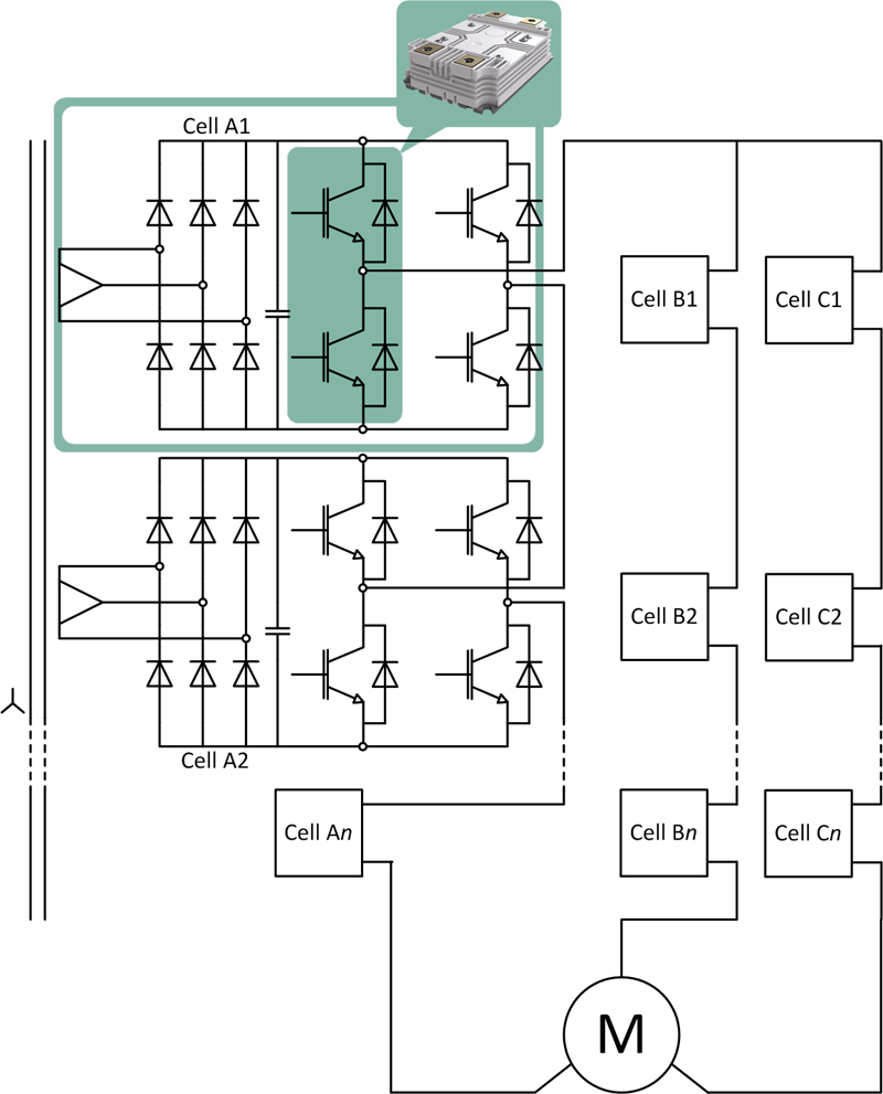
The cascaded cell inverter is an example of a multilevel topology that is now used in drivetrain technologies. Developed by Robicon in the 1990s [2], the separate DC links for each cell are a special feature of this kind of topology. This requires a transformer with a corresponding number of output windings. Nevertheless, because of the simple structure relative to other multilevel medium voltage converters, this topology is very popular. It can be used to make inexpensive converters, especially for pump and ventilator drives with motor voltages between 2.3 kV and 13.8 kV. In this process, at least three cells are set up in series and IGBT modules with a nominal voltage of 1700 V are used (see Figure 4).
Click image to enlarge
Figure 4: Cascaded cell inverter. A compact design of any cell can be realized with a device such as the half-bridge module from Infineon.
For motor voltages of 6 kV or higher, the use of IGBTs with a higher nominal voltage is also reasonable, since they allow the number of cells and insulated transformer windings to be limited. The module from Infineon allows very compact construction of identical cells and enables an identical parts concept that optimizes system costs across a broad performance spectrum.
References:
[1] José Rodríguez, Jih-Sheng Lai, Fang Zheng Peng: “Multilevel Inverters: ‘A Survey of Topologies, Controls, and Applications’”, IEEE TRANSACTIONS ON INDUSTRIAL ELECTRONICS, VOL. 49, NO. 4, AUGUST 2002
[2] P.W. Hammond, “Medium voltage PWM drive and method,” U.S. Patent
5 625 545, April 1997.