System solutions for battery-powered applications: Part 3 of 4 Editorial Series sponsored by Infineon; Maximizing integration and addressing EMI challenges in low-voltage motor drive/control applications
Fully programmable solutions that help deliver ergonomic, compact, and powerful battery-powered tools
Introduction
Now that the era of the IoT, AI, and 5G has arrived, intelligent, lightweight, and miniaturized motor drives are essential to the next generation of power tools. According to a forecast provided by Grandview Research [1], the global power tool market is projected to reach 40.9 billion US dollars in 2027.
Brushless DC (BLDC) are motors currently used in a wide range of battery-powered tools, from drills and screwdrivers to saws, as well as gardening tools such as blowers and lawnmowers.
These tools utilize a variety of electric motors, and brushed motors are gradually being replaced with brushless designs to provide greater reliability. Given the range of battery voltages and power ratings used, many different BLDC motor sizes, shapes and specifications are found in these products.
The Infineon MOTIX™ family of low-voltage motor control solutions has recently added the MOTIX™ 6EDL7141 and MOTIX™ IMD700A [1] three-phase smart motor drivers, which have been developed for battery-powered DIY BLDC motor drives operating from battery voltages in the 12 to 48 V range.
This article describes how integrated control solutions can support the design of motor drive systems to overcome main challenges and deliver state-of-the-art tools in many different applications such as drills, screwdrivers, saws, weeders, hedge trimmers, blowers and robots. In addition, the importance of rotor position sensors, namely Infineon’s XENSIV™angle sensors (TLI5012B) and Hall Latches (TLx4961/68), has to be highlighted. They can largely boost the efficiency of the BLDC driving system reduce the torque ripple but also smoothen the motor rotation and contribute to the overall efficiency by extending the battery runtime.
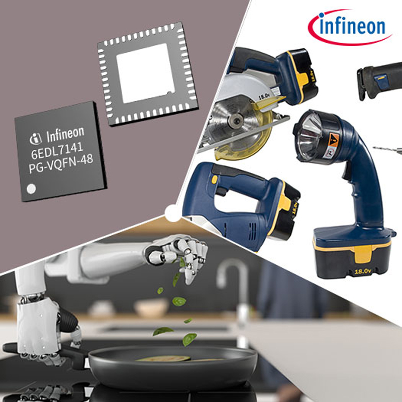
Click image to enlarge
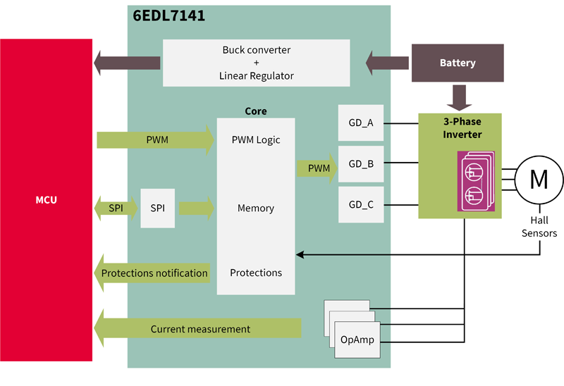
Figure 1.Applications for MOTIX™ 6EDL7141 and MOTIX™ IMD700A
ICs that enable simplified and reconfigurable development of high-performance systems for battery-operated products
The MOTIX™ 6EDL7141 is housed in a 7x7 mm 48-pin VQFN package, and the MOTIX™ IMD700A in a 9x9 mm 64-pin VQFN package, both with exposed bottom side thermal pads. Many key system functions are integrated into these single packages, including configurable gate drivers able to operate up to 100 percent duty cycle, a buck regulator, a linear regulator, as well as current-sense amplifiers and protection circuitry.
The MOTIX™ IMD700A combines all of the features of the MOTIX™ 6EDL7141 with an additional microcontroller whose peripherals and specifications meet the requirements for motor control applications. High integration enables designers to significantly reduce component count, circuit board area and simplify routing, which helps to meet the challenges of housing motor drives in small and awkwardly shaped cavities found in tools and robots. At the same time, component count and board size reduction also enable bill-of-materials (BOM) and assembly cost savings, additionally bringing environmental benefits since fewer materials are used that will eventually be disposed of.
The MOTIX™ 6EDL7141 and IMD700A are also highly configurable, with more than 50 device parameters able to be set from a user-friendly GUI tool, which interfaces with a PC through an SPI interface connected via a USB port. Configuration parameters can be stored temporarily or permanently on these devices.
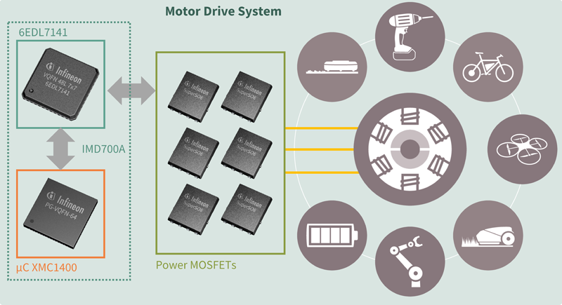
Click image to enlarge
Figure 2. High integration and functionality of Infineon’s MOTIX™ smart drivers
The MOTIX™ 6EDL7141 is designed to operate in conjunction with an external microcontroller such as an Infineon’s XMC1400 series, which is based on a 32-bit Arm® Cortex®-M0 core with a math coprocessor optimized for low-cost embedded control applications such as motor control, power conversion, and LED Lighting applications and human-machine interface (HMI). As mentioned, the XMC1400 controller is integrated into the MOTIX™ IMD700A and combined with the 6EDL7141 in a single package.
Consisting of a three-phase digitally-configurable half-bridge gate driver able to operate in multiple PWM modes, MOTIX™ 6EDL7141 allows the designer to provide all gate drive signals from the microcontroller or provide a simple PWM signal, which can be decoded by the internal logic.
All of these benefits combined greatly simplify the design process and reduce product development time to market.
Programmable gate drivers and parameterization for minimized electromagnetic interface (EMI)
The gate drive outputs can be connected directly to the MOSFET gate terminals eliminating resistor and diode gate driver circuits. Drive sink and source currents can be configured to optimize switching based on the MOSFET characteristics and enable performance tuning. In addition, EMI can also be optimized without changing any components.
The integrated DC-DC synchronous buck converter can supply up to 300 mA with overload protection and requires only a small external inductor and capacitor. The low drop-out linear voltage regulator fed from the buck regulator output supplies a clean digital bus voltage selectable to 3.3 V or 5 V to supply the microcontroller. The linear regulator also incorporates overcurrent protection and an overcurrent pre-warning function, which can be communicated to the micro-controller through an open-drain digital output pin.
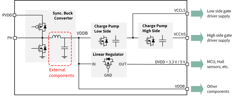
The three-phase gate driver section of the MOTIX™ 6EDL7141 is supplied by the low and high side charge pumps, as shown in the block diagram of Figure 3. Each charge pump uses an external switched capacitor to transfer charge from the buck converter output to the gate driver bias supplies: VCC_LS and VCC_HS. VCC_LS is referenced to the system zero volt rail, and VCC_HS is referenced to the system positive supply rail. Tests have shown that the buck regulator is a significant source of EMI in motor drives. Therefore the charge pump clock frequency is configurable between 166 and 1800 kHz with additional frequency modulation to reduce EMI.
Click image to enlarge
Figure 3. MOTIX™ 6EDL7141 integrated power supplies block diagram
Charge pumps used as an alternative to high side bootstrap circuits (commonly used in half-bridge drivers) allow full gate drive duty cycle up to 100 percent, which is necessary to provide maximum motor drive output. The sync buck is able to deliver 6.5, 7, or 8 V output depending on the selected gate drive voltage, which the user may configure as 7, 10, 12, or 15 V. The charge pump structure enables these voltage levels to be maintained even if the battery voltage drops to a lower level.
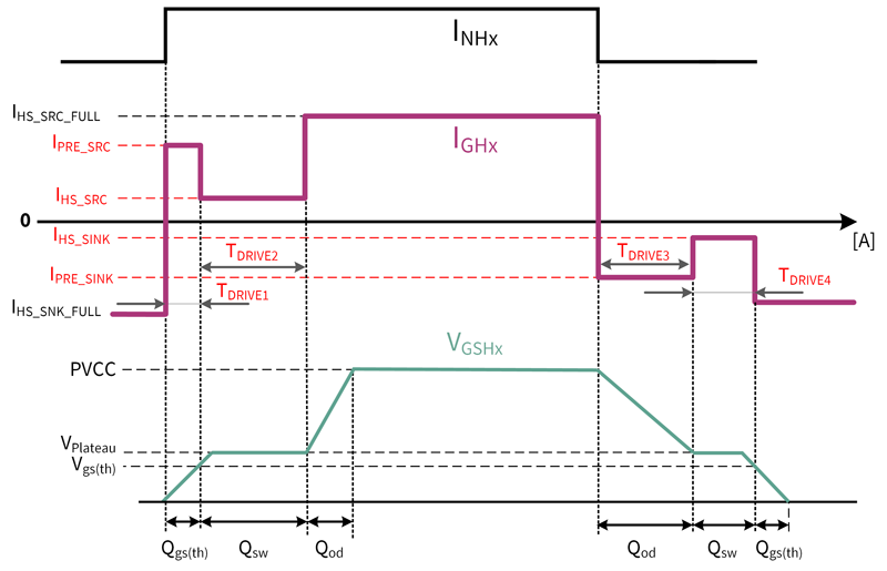
The fixed ground of the high-side enables high accuracy of current sensing and control of the gate drive sink and source currents in small steps to allow precise di/dt adjustment. These adjustments affect the half-bridge voltage slew rate, which significantly impacts the EMI produced by high-frequency switching. The rise and fall slew rates are separately controlled by adjusting the gate drive sink and source currents during defined time segments during the switch on and switch off processes. The fall time is one of the most important parameters for optimizing drive systems since it affects critical factors like switching losses, dead time optimization and drain voltage ringing, which can lead to possible MOSFET avalanching or excessive EMI emissions.
Click image to enlarge
Figure 4. Configurable gate drive output optimizes gate drive
EMI management by the digital configuration of the gate drive is a major advantage of the MOTIX™ 6EDL7141 and IMD700A, enabling optimization at the EMI test facility without needing to change any components on the board.
In a typical system, several key components produce EMI emission during switching:
1. PWM dV/dt at the phase switching nodes:
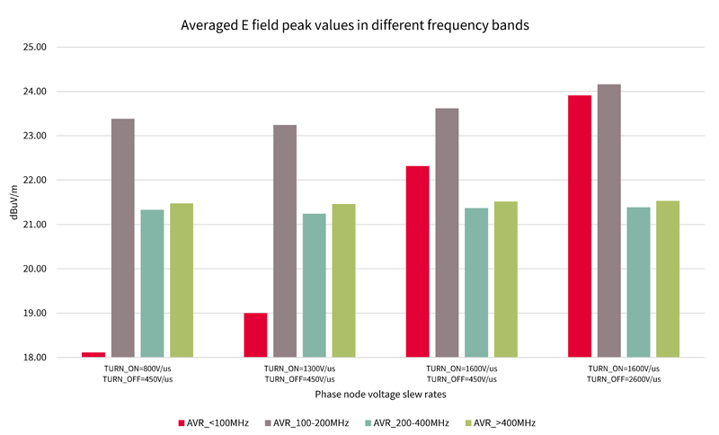
The PWM switching waveform contains a high content of mostly odd harmonics. The harmonic content level depends on the switching transition speed, dV/dt. The majority of these harmonic contents can go as high as the 15th harmonic, which falls in the 5 MHz region of the frequency spectrum. The most problematic harmonics are the 2nd to 5th harmonics that fall within the range of 500 kHz to 1.7 MHz. EMI test results shown in Figure 5 demonstrate that different dV/dt values give rise to emissions in different frequency ranges. Lower dV/dt helps reduce EMI emissions; however, the tradeoff between EMI compliance and switching losses affecting MOSFET operating temperature needs to be found.
Click image to enlarge
Figure 5.EMI comparison test at different dV/dt
2. Narrow high peak current followed by oscillatory ringing from LC resonance:
The oscillatory ringing produced by stray inductances and capacitances causes common-mode conducted EMI emissions in the 100 MHz range. A good grounding system is required to close the noise source with a common mode filter. The MOTIX™ family smart motor driver’s high integration makes the board’s ground layout easier and tighter.
3. MOSFET body diode recovery:
Another primary source of EMI is the body diode Qrr of the MOSFETs in hard-switching operation. This noise generally appears in the 50 to 150 MHz range and depends on how tight the current loop is. This current loop is formed around the high and low side FETs and bus capacitor(s) between the drain of the high-side and the source of the low-side. Qrr is the energy source that triggers an LC resonant circuit to ring. The L elements originate from stray inductances in the MOSFET packages and also PCB traces, while the C element mostly comes from the MOSFET Coss. The high density of circuit functions and configurable smart gate driver controller leave more flexibility for MOSFET selection and reduce PCB layout size, which can minimize the EMI caused by Qrr. In addition to the well-explained MOTIX™ product family, Infineon offers an extensive range of further product families, suited or dedicated to power tool applications. These include XENSIV™ sensors (e.g., Hall switches such as the TLE496X, Angle sensors such as the TLI5012B), power MOSFETs (e.g., OptiMOS™, StrongIRFET™ 2 or CoolMOS™ in various packages), EiceDRIVER™ gate driver ICs, OPTIGA™ embedded security solutions, microcontrollers such as 32-bit PSoC™ Arm® Cortex® μCs and XMC™ industrial μCs based on Arm® Cortex®-M, EZ-PD™ USB-C and Power Delivery solutions and many more. Details can be found in [5].
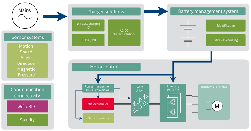
Click image to enlarge
Figure 5: Cordless power tools: Applications block diagram example
Summary
The MOTIX™ series smart three-phase gate drivers 6EDL7141 and IMD700A offer a high level of integration and flexible parameterization with dedicated functionality for motor drives, which greatly simplifies PCB layout and reduces EMI emission.
Besides a very significant component count saving enabling space reduction, the task of optimizing the inverter performance and EMI compliance is made less time-consuming and more convenient for the system design engineer by means of the computer-based simple-to-use device configuration GUI tool.
To explore Infineon’s broad solution portfolio for motor controller ICs, and learn more from dedicated product datasheets, application notes, and training videos, make sure to visit our Battery Supplied BLDC Motor Controller ICs and Motor Control ICs related web pages.
References:
[1] Market Research Reports & Consulting, Grand View Research, Inc., “Power tools market size worth $40.9 billion by 2027. ” June 2020, Grandview Research [Online]. Available:
https://www.grandviewresearch.com/press-release/global-power-tools-market
[2] Infineon Technologies, “Datasheet 6EDL7141,” Revision 1.04, October 2021 [Online]. Available: https://www.infineon.com/dgdl/Infineon-6EDL7141-DataSheet-v01_04-EN.pdf?fileId=5546d46279cccfdb0179f4c1d3bf0756
[3] Green, P., Voskanyan, S., “EVAL_6EDL7141_TRAP_1SH 18 V brushless DC motor drive board,” Application Note AN_2104_PL88_2104_024859, version 1.1, November 2021, Infineon Technologies [Online]. Available: https://www.infineon.com/dgdl/Infineon-Evaluation_board_EVAL_6EDL7141_TRAP_1SH-ApplicationNotes-v01_01-EN.pdf?fileId=5546d46279cccfdb017a0ae054e624bd&da=t
[4] Green, P., “Smart Gate Driver IC Simplifies Motor Drive Design In Battery-Powered Applications,” How2Power.com [Online]. Available: http://www.how2power.com/newsletters/2109/articles/H2PToday2109_design_Infineon.pdf
[5 ] Infineon Technologies, “Cordless power tools. Innovative, Reliable, Handy,” Application Brief, May 2021 [Online]. Available: link
[1] Coming soon! To be released in Q3, CY 2022