Author:
Timur Uludag, Senior Technical Marketing Manager MagI³C Power Modules Würth Elektronik eiSos
Date
04/01/2021
 PDF
PDF
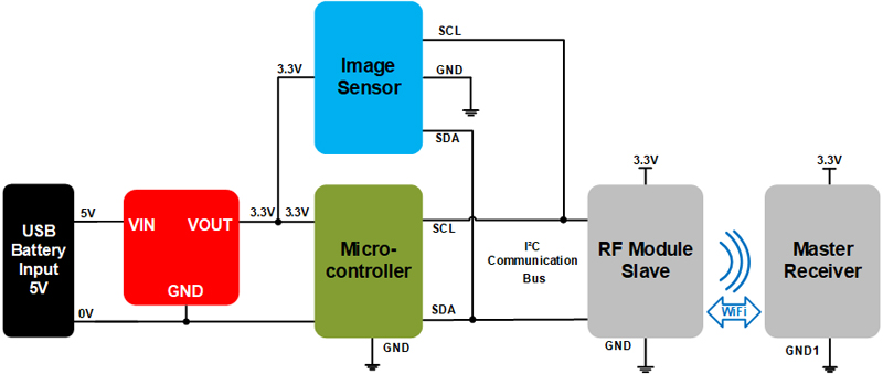
Figure 1: Block diagram of a security camera application
Space constrained applications like portable devices require especially designed DC/DC converters with a certain set of characteristics. Tight space, by definition, requires tiny DC/DC converters which have excellent thermal performance. This article digs deeper into the challenges that arise for the power supply of space-constrained applications and how they can be overcome.
Space Constrained Applications
To get a better overview of the requirements of an industrial space constrained application we take a closer look at the example of a security camera system with its functional units.
Description of the application:
The application consists of an energy source, a DC/DC converter, an image sensor, an MCU unit and WiFi communication devices. The DC/DC converter regulates the 5 V that comes from the battery or the USB port to 3.3 V, providing a stable regulated power to the MCU. The MCU processes data, initiates follow-up actions and sends commands to the sensor and the WiFi communication module. The RF Module (slave) then sends the data from the image sensor via WiFi to the master receiver unit. From there the data will be processed and visualized on a display.
Now that we know how a space constrained application is structured, what challenges for the DC/DC converters can be derived from the structure? The table below shows the most important obstacles that need to be considered during space constrained DC/DC converter design and how these can be countered with the use of compact power modules.

Click image to enlarge
Table 1: Challenges and solutions during a DC/DC converter design phase
To realize the solutions with a DC/DC converter we need to better understand the design process of the converter.
Tiny and compact MicroModules – Advantages for the use of power modules during design-in
Space constrained inherently means the available design space for the system is limited as illustrated by the security camera application. Therefore, the optimum design is characterized by the best usage of that available system volume to meet the power demands of the application.
The design of a discrete converter requires at least the following steps:
§ Design of the DC/DC converter itself
o Select the topology
o Select the controller IC
o Calculate and select the power parts (MOSFET, Diode, Inductor)
o Calculate and select the input and output capacitors
§ Test bench development
§ Optimization for stable regulation over the entire input/output voltage and load current range
§ Layout routing for good EMI and thermal performance
§ Validation of the overall design for easy manufacturing
§ Pre compliance tests for EMI and safety
§ Logistic chain and production security
All of the discrete DC/DC converter design steps mentioned before have already been performed in a MagI³C power module. The EMI and thermal performance can be estimated in advance with the online designing tool REDEXPERT. These facts allows designers to simply select a module based on the electrical specifications of the application and therefore get rid of all the above mentioned design steps. Therefore, a power module enables design engineers to speed up the process of designing a power supply for their system compared to a conventional discrete DC/DC converter.
The use of a power module from the VDMM family shortens the overall time to market while saving design resources. The DC/DC power modules offer a high power density solution designed to offer the most power for the least space.
The next step is to evaluate the basics of the switching behaviour of the DC/DC power module, which is the solution for most of the mentioned challenges.
Battery powered applications like portable devices do not always operate under full load conditions. If we look at a measurement application, there is a higher current demand during measuring and a lower one between the measurement instances.
Therefore, the power management has to be flexible enough to offer the best performance during each load situation.
Two different load situations are present:
§ Light load – application works in idle or standby mode reduced energy consumption
§ Heavy load – application works under nominal conditions nominal energy consumption
Therefore, power management should adapt to the load situation to offer the best efficiency and performance.
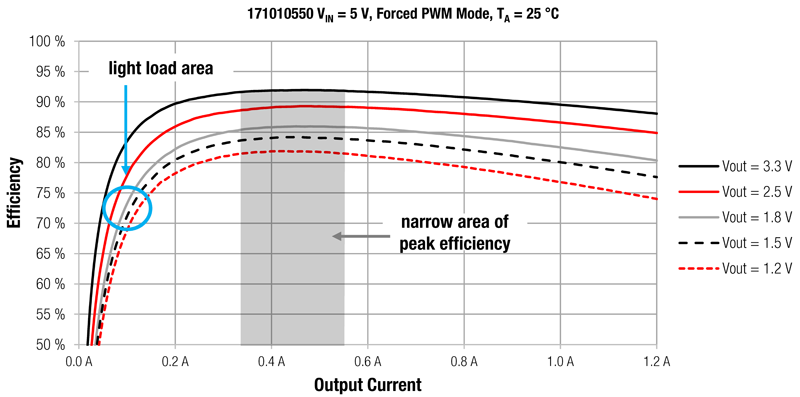
Figure 2 and Figure 3 show the efficiency of the 1.2 A MicroModule WE MagI3C Power Module 171010550, as an example of the different load situations discussed above. In figure 2, we can see the “typical” behaviour that we expect from standard buck converters operating in pulse width modulation (PWM) mode. Forced PWM mode is widely used and this mode is present in the majority of industrial power supplies. This mode is satisfactory for this type of application as they work in heavy load conditions for the majority of their operating lifetime. However, applications like sensors have a different load situation. Here, the light load condition is the predominant operating situation. Therefore, the switching behaviour has to be modified to perform optimally during this load situation.
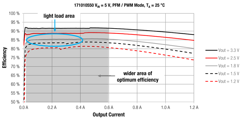
Pulse frequency modulation (PFM) mode clearly offers higher efficiency values as the load current decreases. This supports a longer lifetime of the battery in battery powered devices.
Forced PWM Mode:
Click image to enlarge
Figure 2: Forced PWM mode efficiency in dependence of different load conditions, WE MagI3C Power Module 171010550
PFM / PWM Mode:
Click image to enlarge
Figure 3: PFM / PWM mode efficiency, WE MagI3C Power Module 171010550
If we take the grey Vout = 1.8 V curve, the transition between PFM mode and PWM mode is around 400 mA. The point at which the transition happens depends on the output voltage and the input voltage.
Click image to enlarge
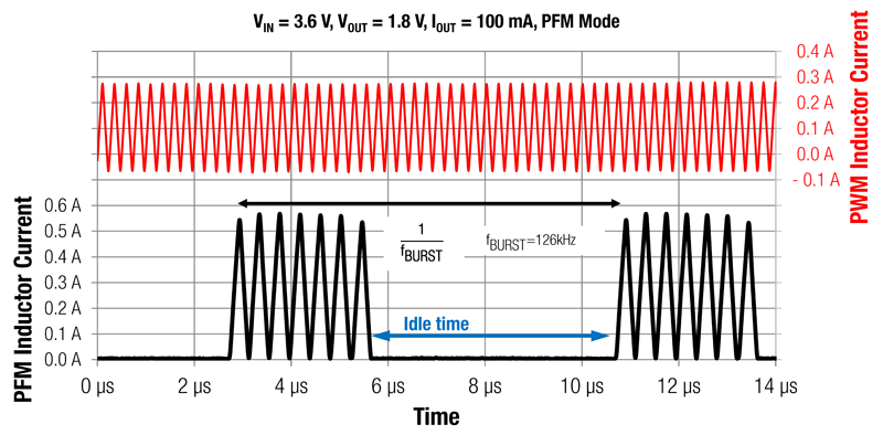
Figure 4: Comparison between PWM and PFM mode,WE MagI3C Power Module 171010550
Description of the switching behaviour:
Figure 4 compares the inductor current of the module WE 171010550 during PWM and PFM behaviour. The inductor current switches in bursts when operating in PFM mode. Both the load and the output capacitor are supplied with energy during each burst. During the idle time (the time between two burst actions) both switches, the high side and the low side, are switched off. This leaves the output capacitor to supply the load current entirely by itself. Therefore, the energy consumption of the module between two burst actions drops dramatically until the feedback system triggers the next burst action. In turn, the efficiency in PFM mode is significantly higher compared to that of traditional PWM mode due to less switching losses. The idle time is inversely proportional to the load current, i.e. if the load current increases, the time between the burst actions decreases. The module switches back from PFM to PWM mode when the idle time approaches zero, returning to constant switching behaviour at the default switching frequency of 4 MHz.
The peak inductor current during PFM mode is higher than in PWM mode, allowing the same amount of energy to be delivered to the load in a fixed period of time while decreasing the losses generated within the converter. During the idle time in burst mode the module produces no losses compared to the PWM mode
Output voltage ripple:
If the output voltage is higher than a certain value both switches remain off. During the idle time only the output capacitor supplies the load current, meaning the output voltage will drop. When the output voltage drops to a certain level the next burst cycle starts. The resulting value of the ripple depends on the threshold value that is set internally by the controller IC. The output voltage ripple during PFM mode can be reduced by simply increasing the output capacitor. The max value for the output capacitor can be found in the corresponding datasheet of the power module.
The phrase ‘space constrained’ does not mean that there is only one DC/DC power module that will fit every application. Each application has its own power supply requirements. To address the numerous possible demands of space constrained applications, a family of DC/DC power modules is needed. Each family member has its specialisation, allowing for flexibility based on various design and production parameters.
Click image to enlarge
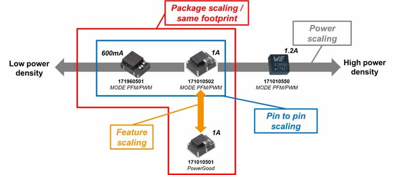
Figure 5: Dimensions of scaling, variety of different designs, WE MagI3C Power Modules
Figure 5 shows the members of the MagI³C VDMM family in their various design and production dimensions.
Package scaling / same footprint (red)
Due to thepin and package compatibility, the designer has the freedom to evaluate the application from 600mA to 1A by simple changing the power module. The layout stays the same in both options. With a minor change in layout to accommodate the power good feature of the WE MagI3C171010501 module, a third module can be seen as nearly pin compatible.
Power scaling (grey)
Today, applications are constantly demanding higher power levels with decreasing board space. For rising power demands, the designer can choose to get from 600mA up to 1.2A in tiny form factors.
Pin to pin scaling: (blue)
For a 100% one to one replacement the designer can choose between the 600mA 171960501 and the 1A 171010502 WE MagI3Cpower modules.
Feature scaling: (orange)
Depending on the specific needs for an application’s power supply, the designer can choose between output voltage status monitoring with the 171010501 WE MagI3Cpower module and active efficiency control with the 171010502 WE MagI3Cpower module.
In summary power modules like the MagI3C series provide proven, tested, reliable and compact solutions to space constrained and budget constrained projects. They incorporate the latest advancements in technology like the combination of PFM/PWM modes which offers better efficiency at lighter loads and optimal efficiency over the entire load range. This makes them ideally suited to applications that are battery powered. The proliferation of IoT sensor applications, that read and transmit data only periodically is an example that benefits from the automatic transition from PFM to PWM modes between quiescent and active states. And, sometimes the module can do the seemingly impossible…answer the last minute request for more power from the same space!