Circuit protection using gas discharge tubes
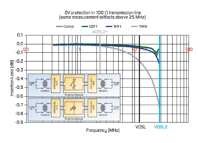
Telecommunications equipment must be able to survive surges and power faults as defined in the relevant standards. Survivability can be achieved by providing protection either remotely or at the terminals of the equipment, or both. In addition, or alternatively, protection can be achieved by making the equipment more robust. When designing a circuit protection strategy, it is important to consider the complete system. To reduce cost, the capabilities of the protection scheme may be diminished, but other components must then be made more robust to compensate. In such a case, the cost of enhancing reliability of the downstream components may exceed the cost savings of a less robust protector. A good design will optimize the trade-offs. VDSL circuit protection considerations VDSL (very-high-speed digital subscriber line) technology facilitates the delivery of information at speeds of up to 52Mb/s. Standard VDSL deployment uses a frequency spectrum up to 12MHz, whereas VDSL2 allows for up to 30 MHz as an option. The capabilities of VDSL are dependent on the distance between the operator and end-customer equipment, as well as the condition of the existing copper plant and copper infrastructure outside the plant. Depending on loop conditions, VDSL is able to support varying bit rates and high bandwidth services, such as a channel of HDTV programming, over telephone copper pairs. Since VDSL equipment connects to the copper infrastructure of the Public Switched Telephone Network (PSTN), the equipment may be exposed to overcurrent and overvoltage hazards from AC power cross, power induction, and lightning surges. Resettable PPTC (polymeric positive temperature coefficient) overcurrent protection devices can be used in a coordinated protection scheme with overvoltage devices - such as gas discharge tubes (GDTs) and thyristor surge suppression devices - to help reduce equipment failures and warranty costs. Reducing insertion and return loss Because signal spectrum is increasing from 10 MHz to 30 MHz, VDSL system designers are faced with a number of new challenges. The most important issue is reducing insertion and return loss and the effect on reach and rates in high-speed applications. The capacitance of overvoltage protection devices becomes a concern in the upper range of the VDSL frequency spectrum, as the devices used to protect the system may cause increased system insertion loss. Testing by Tyco Electronics has shown that low-capacitance thyristors and GDTs are suitable for high data rate circuits, including VDSL applications. Figure 1 illustrates the capacitance effects on insertion loss of several overvoltage protection configurations. It shows that low capacitance GDTs (1pF) have the lowest insertion loss, with the standard 50A thyristors (15pF at 50V DC bias) and 100A microcapacitance devices (20pF at 50V DC bias) having slightly greater insertion loss. The inset modules shown in this test diagram consist of either a 230V 3-Pole GDT or two 270V in-series thyristors, attached to two 0.3m pieces of Cat 5e twisted pair. An Agilent 8753ES Vector Network Analyzer with two North Hills' 0301BB 50:100 Ohm wide band transformers were used to make the insertion loss measurements. The transformers were used to measure the insertion loss of the modules under 100 Ohm impedance conditions, which is equal to the line impedance over the VDSL frequency spectrum. Capacitance at 1MHz with no bias was measured using an HP 4195 Low Frequency Impedance Analyzer.
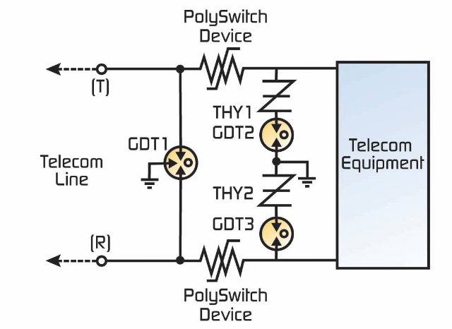
Implementing a low-capacitance solution for VDSL The circuit diagram in Figure 2 shows a VDSL solution that effectively reduces capacitance and energy let-through, and optimizes the circuit protection scheme. As shown in this circuit diagram, GDT1 provides primary protection (at 350V to 1000V). The GDT2 and GDT3 devices are connected in series with the thyristors. In this scenario, the thyristor helps lower the breakdown voltage of the GDT and reduces the let-through energy in the case of a surge. The PolySwitch™ PPTC devices help coordinate the primary and secondary protection.
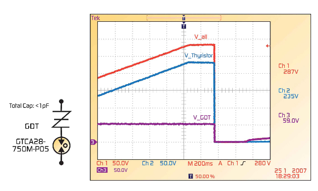
Figures 3, 4 and 5 show test results for this protection method and demonstrate that the GDT and thyristor combination does not break down under ringing voltage and does not clip the ringing voltage. In the oscilloscope screen shot in Figure 3, the input voltage rate is at 100V/s. The DC breakdown voltage at 287V is achieved, which is higher than the ringing voltage of 200V.
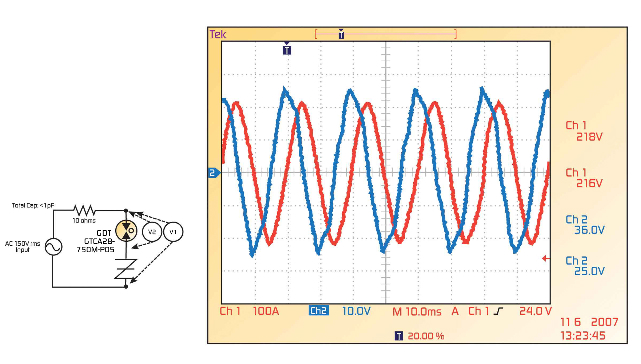
Figure 4 shows the data from a test performed with an AC voltage input at 150Vrms. Results show no clipping, indicating that the GDT and thyristor combination does not break down under the ringing voltage and clip the ringing voltage. Here, the thyristor determines the static breakdown.
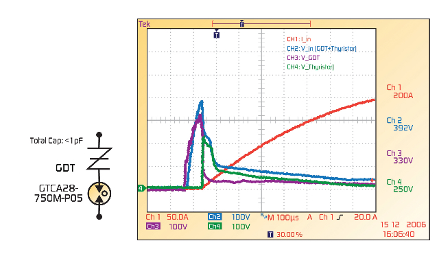
In Figure 5, the same test was performed per the ITU K.20 10/700?S at 4kV level. Oscilloscope observations show the breakdown voltage of the GDT and thyristor combination at 392V. Voltages also noted are the GDT breakdown voltage of 330V, and the thyristor breakdown voltage of 250V. Here, the dynamic breakdown voltage is determined by the GDT. Summary GDTs are commonly used to help protect sensitive telecom equipment from damage caused by transient surge voltages that may result from lightning strikes and equipment switching operations. GDTs are placed in front of, and in parallel with, the sensitive equipment acting as a high impedance component while not influencing the signal in normal operation. Due to their low capacitance, GDTs exhibit lower insertion loss than many other overvoltage protection technologies. Due to their fast and accurate break-over voltage, GDTs are suitable for applications such as MDF (Main Distribution Frame) modules, high data-rate telecom applications (e.g., VDSL and xDSL), and surge protection on power lines. When used in a coordinated protection scheme with PPTC devices and thyristors, they can help equipment manufacturers meet the most stringent regulatory standards. As with any type of protection scheme, the effectiveness of a solution will depend on the individual layout, board type, specific components, and unique design considerations. Most circuit protection device manufacturers will work with OEM customers to help identify and implement the best approach. www.tycoelectronics.com