Test considerations for variable-frequency drives
The design of motor drive systems is a highly complex affair
Motors are everywhere in our world, it seems. Consider our vehicles, for example. When is the last time you had to hand-crank a car window up and down to pay a highway toll? Or, for that matter, when did you last manually adjust the seat position or rear-view mirror angles? Typically, motors drive all of these aspects of our vehicles these days.
We demand great precision in terms of speed, positioning, and start/stop times in other motor applications. Industrial equipment, UAVs and other military/aerospace systems, and even children’s toys depend on precise motor operation for safety and proper function. For all of these motors, there must be a motor drive system controlling the action.
The design of motor drive systems is a highly complex affair. A commonly encountered motor drive is the variable-frequency drive (VFD), a circuit that converts AC line voltage to DC, and then converts the DC voltage to a pulse-width-modulated AC signal that is applied to the motor terminals. VFDs that operate from a battery input forego the AC rectification. Figure 1 shows a simplified, yet typical schematic of the complete power-conversion section of an AC-AC, three-phase variable-frequency drive (VFD).
About the power section
In the power section (see Figure 1), the three-phase AC line input is rectified by a six-pulse (six-diode) rectifier and filtered to a low-ripple, stable DC bus voltage in the DC Bus/Link section. Also shown are signals present in the circuit at the AC line input, DC bus, motor drive output, and gate drive of the power semiconductor devices. This form of VFD is highly representative of 95% or more of VFD designs.

Click image to enlarge
1. The power section of a motor drive system requires measurements of line input, PWM output, and efficiencies
Input to the VFD is typically a 50/60-Hz, single- or three-phase signal (in the latter case, the phases are typically designated A, B, and C) at a voltage anywhere from a nominal 120 V to nominal 600 V. The three-phase PWM motor drive output, when applied to the motor's winding, induces a near-sinusoidal current to flow in the winding. The characteristics and quality of the output voltage signal is related to the PWM control methodology. Control of the width of the PWM signal results in more or less voltage applied to the winding at a given frequency, resulting in more or less current draw in the motor. The current draw provides the correct speed, torque, power, efficiency, etc. from the motor.
In the above-described power section of the VFD, we want to take measurements on the line input, pulse-width modulation output, and efficiencies. These are primarily low-frequency measurements in the range of 1 to 5 MHz. Ideally, we'd want to correlate power-section behaviors to the high-frequency behaviors of the embedded control system.
Moving ahead to the motor-integration section of the drive system (see Figure 2), there are more measurements related to the motor's torque, speed, position, and power (motor (mechanical) power = torque times speed). These are very low-frequency measurements in the kilohertz range. Here, it's desirable to have a simple means of integration to the measurement instrument(s).

Click image to enlarge
2. Torque, speed, position, and power must be measured in the drive's integration section
Debugging the control section
Debugging of the control section of the motor drive is perhaps the most complex task (see Figure 3). The controller comprises analog and digital signals, serial data, the control loop itself, and PWM signals. Here, we encounter high frequencies of 100 MHz and higher. Mixed-signal debugging and validation of this nature calls for an oscilloscope with a good amount of analysis functionality.

Click image to enlarge
3. Analog, digital, and PWM signals join with serial data and control-loop signals to make debug of the motor drive's control system a highly complex task
A high-voltage isolated gate driver connects the control/logic system to the power electronics. The controls take feedback signals from the motor and other parts of the circuit and then apply algorithms to calculate how the gates of each power transistor should be switching on/off to create the appropriate PWM signal. Because the controls connect to the gates of the power semis, there is no ground reference for many of the signals on the controls. Moreover, the controls themselves are not at ground potential.
One may instrument the motor shaft for position, speed, or torque measurements, and the motor as a whole for current inputs, temperature, vibration, or other physical characteristics. Some of these instrumented signals provide feedback to the VFD control system while others serve only design validation and/or testing.
Variations in PWM techniques
A key differentiator between VFDs is their application of pulse-width modulation (PWM) techniques. Voltage output from the VFD is controlled through a variety of modulation schemes, all of which result in simple single-level PWM gate-drive signals (one per power-semiconductor device) and single-level (or, less commonly, multilevel) signals at the output of each phase of the motor drive. When the output voltage is viewed line-line, this single-level signal is a two-level signal. The PWM drive output signals will vary in quality based on the control and modulation technique chosen for the drive.
In general, users refer to these different control techniques as one of many different “sine-modulated” techniques or a "six-step commutation" technique. A sine-modulated technique applies voltage to all three phases simultaneously whereas a six-step commutation technique applies voltage to two of the three windings at any given time.
The single-level PWM gate-drive signals can be determined and generated through a simple carrier-based method or, for sine-modulated techniques, through a more algorithmically complex space-vector (pulse-width) modulation (SVM or SVPWM) method. Carrier-based PWM methods are simpler to program and implement and are lower in cost but have higher harmonic content. SVM methods call for more implementation skill and carry higher costs (due to a faster and more expensive processor in the VFD's embedded control section) but generate lower harmonic content.
Carrier-based PWM
In carrier-based PWM schemes, the carrier (high) frequency is most often a triangle wave and the modulating (low-frequency speed control) signal is a sine wave. You will often find this approach used in simple scalar V/f (sine-modulated) and six-step commutation controls.
The sinusoidal intersective carrier-based PWM method is the most widely used approach in new designs. This method uses a constant-amplitude, high frequency (~1-100 kHz) carrier and a low-frequency control of ~60 Hz, or the desired VFD output frequency, with fixed or varying amplitude. The intersection of the modulating sine wave with the carrier frequency creates the width-modulated signal. Look at a simple example of PWM for a single power-semiconducting device in which the PWM signal has a 50% duty cycle at zero volts of the modulating signal (see Figure 4).

Click image to enlarge
4. An example of PWM for a single power semiconductor
The carrier frequency can either be a triangle or saw tooth waveform; this defines the intersection with the modulating waveform for purposes of width determination. The example in Figure 4 is for a triangle waveform, but the frequency was less than 1 kHz (i.e., illustrative only) so that the signal could be more easily viewed with a modulating signal of lower frequency.
For full-bridge or half-bridge power-conversion systems, the upper and lower devices switch independently. Thus, the PWM waveforms for each device are a bit more complicated to "view" and to understand how they relate to the power-conversion devices or drive's output, but the basic concept is the same.
For example, in a half-bridge configuration, there is an upper and lower device; both switch in a complementary fashion to create the full output waveform. In Figure 5, the upper device's PWM waveform is at top, the lower device's PWM waveform is at center, and the total output (upper minus lower) PWM waveform is at bottom (the modulating and carrier-frequency waveforms are omitted in this example but they are the same as in Figure 4).

Click image to enlarge
5. PWM waveforms for a half-bridge power conversion system
In a full-bridge, or H-bridge, design, the upper and lower waveforms and output PWM waveforms appear as shown in Figure 6. For a three-phase design, one modulating signal is created in the microcontroller and then phase-shifted by 120° or 240° to create the other two modulating signals for the other two phases.
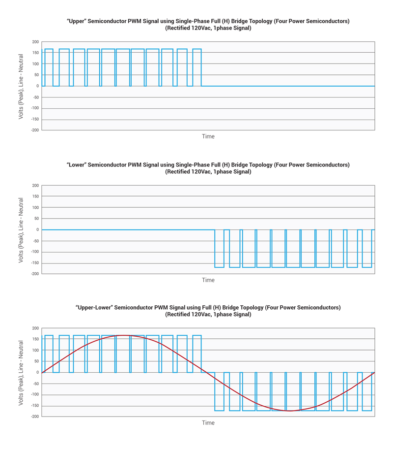
Click image to enlarge
6. PWM waveforms for a full-bridge power conversion system
Note that both series power-semiconductor devices in a half-bridge, full-bridge, or cascaded H-bridge topology cannot be switching on at the same time, which may result in "shoot-through" and device failure. Thus, some minimum dead time before and after switching is built into the controls to avoid having both devices switched on simultaneously.
Space vector (Pulse-Width) modulation (SVM or SVPWM)
In SVM, a matrix transformation is used to transform a three-phase voltage signal that corresponds to the rotating stator magnetic field into a single rotating "space vector" in a two-dimensional reference frame. This simplifies calculation of a single voltage magnitude and angle, which is then inverse-transformed back to a three-phase voltage signal for generation of the gate-drive PWM signals.
SVM is a more algorithmically complex modulation scheme compared to a conventional carrier-based PWM, but it allows suppression of certain harmonics for an overall improvement of the VFD's harmonic performance. There are several variants of space-vector modulation based on the alignment of the pulse widths within a defined "time slot." However, in the final analysis, the VFD's PWM output signals look essentially the same as with carrier-based PWM schemes.