Anti-islanding in power grid applications
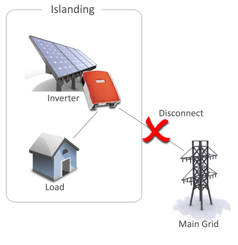
Figure 1: Islanding
PV is becoming pervasive, but there are vital safety considerations that need to be adhered to - and tested thoroughly Introduction to islanding Islanding of photovoltaic systems is a phenomenon that occurs when the solar inverter and a connected load are disconnected from the main grid and subsequently form an "island" (Fig 1). In situations where the load circuit inside such an island resonates at the same frequency as the utility grid itself, the solar inverter may not detect the disconnection from the grid, and will continue to power the island. This effect can be used intentionally to provide a power back-up system for buildings that normally sell their power to the grid. However, for photovoltaic systems dedicated to supplying power to the grid, this effect is unwanted, and can potentially lead to an unsafe situation and damage to equipment.
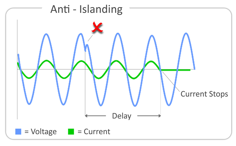
Protection from dangerous situations In such a scenario, utility workers may not realise that an electric circuit is still powered by the solar inverter after they disconnect it from the utility grid: a situation that imposes an immediate danger on the engineers. Moreover, the inverter and loads may be damaged if there is an unsynchronised reconnection to the grid. For this reason, solar inverters that are designed to only supply power to the grid are generally required to have automatic "anti-islanding" functionality. Anti-islanding If a disconnection from the grid occurs, a voltage drop, frequency change or phase shift of the output voltage is normally detected by the inverter, which will subsequently stop generating current. This is known as "anti-islanding", and an example is shown in Fig.2, in which a phase shift suddenly occurs on the inverter voltage output, and within a specified time the inverter shuts off the current.
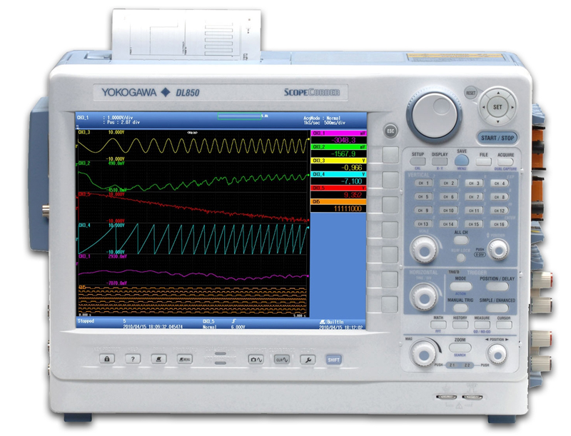
Testing the anti-islanding function Testing the anti-islanding function during manufacturing of the solar inverter is essential to ensure that the system operates correctly in "real life" conditions. However, setting up a measuring device to trigger on a small voltage drop, frequency change or phase shift can be quite a challenge as a standard voltage level trigger - as used in typical modern test instruments - is not sufficient for this task. The solution to this challenge is provided by the Yokogawa DL850 ScopeCorder (Fig.3), which is equipped with a set of dedicated application triggers.
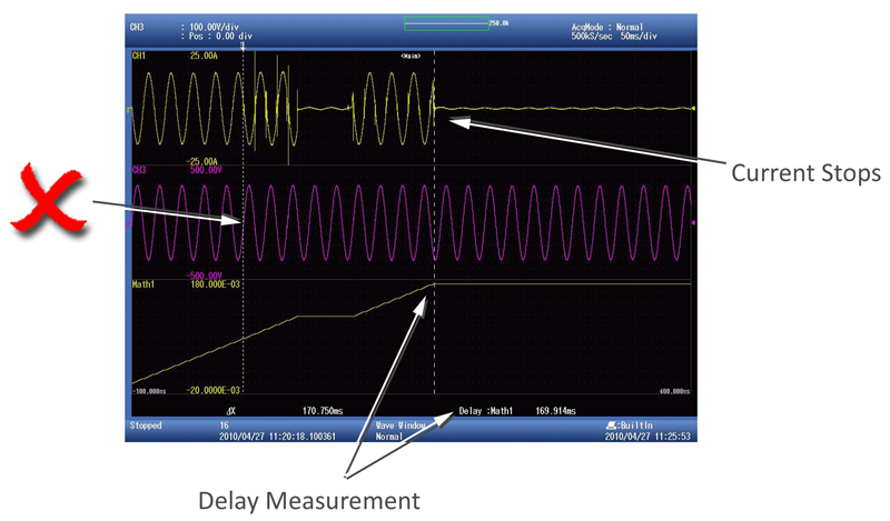
To detect the disconnection from the grid, the "wave window" trigger of the DL850 is used. This type of triggering is useful for any AC power line test where a trigger is required when a sag, impulse, dropout or frequency/phase change on a power line occurs. To detect the point where the current output stops, a combination of mathematical functions is used to automatically detect the point where the current drops. This result is then used to automatically measure the delay time (Fig.4). The DL850 ScopeCorder is a versatile instrument that combines the benefits of a high-speed oscilloscope and those of a traditional data-acquisition recorder in a single, portable instrument. It also incorporates a number of features that make it ideally suited to tests on renewable energy systems. As an oscilloscope, the DL850 brings features like high sample rate (up to 100 MS/s), special triggers to capture transient events, and analysis tools; as a data-acquisition recorder, it implements high channel count (up to 128 channels), isolated high-voltage inputs (with up to 1 kV optical isolation), and a large acquisition memory to measure for longer periods of time. This combination of features makes the instrument particularly suited to carrying out tests on the inverters and associated power electronics used with wind, solar and tidal power generators. www.tmi.yokogawa.com