Like many types of sensors, thermocouples can struggle with a common problem
Thermocouples are a commonly used type of temperature sensor that give accurate readings in applications ranging from lab test benches to industrial environments. Like many types of sensors, thermocouples can struggle with a common problem: the issue of acquiring accurate data. Before improving the accuracy of thermocouple readings, one should understand how thermocouples are constructed and the physics behind how they work.
The Physics of Thermocouples
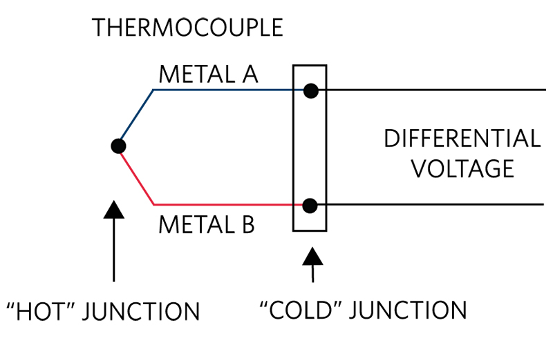
A thermocouple is created when there is a combination of two dissimilar conductors forming a “hot” and a “cold” junction as shown in Figure 1. If the two junctions are maintained at different temperatures, the result is the production of an electromotive force (EMF). That EMF, also known as the thermoelectric voltage, is measured in the millivolts range and is the product of a physical phenomenon known as the Seebeck effect. The Seebeck effect describes the voltage that results from the thermocouple materials and the temperature difference between the hot and cold junctions.
A linear approximation of the Seebeck effect can be seen in Equation 1.
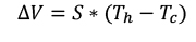 (Eq 1)
∆V- Voltage difference between two dissimilar metals
S - Seebeck coefficient in V/K (commonly in µV/°C)
Th - Tc - Temperature difference between hot and cold junctions
The Seebeck coefficient is specific to the two conductors that are used to construct the thermocouple, and has a non-linear dependence on the temperature. Using a linear approximation of the Seebeck effect can produce significant measurement errors, and modern thermocouple measurement techniques should take this non-linearity into account. It is important to understand that a temperature measurement cannot be determined solely from the EMF generated by the thermocouple. Instead, the following three parameters must be known:
1. The thermoelectric voltage due to thermal gradient between the hot and cold junctions
2. The thermocouple type
3. The cold junction temperature
Without knowing these variables, the temperature cannot be determined at the thermocouple sensing junction. An updated calculation for measuring the temperature at the hot junction of a thermocouple, taking the above parameters into account, is shown in Equation 2:

Th - the hot junction temperature in °C
Tc - the cold junction temperature in °C
a(Tc) - Seebeck coefficient as a function of Tc in µV/°C
Accuracy of Thermocouple Readings
With the fundamentals in mind, it is easier to understand the factors that can affect the accuracy of thermocouple measurements. Hot junction temperature measurements from a thermocouple are not hard to generate when given the three necessary parameters above. However, the method for acquiring these parameters may introduce inaccuracies into the measurement. The following factors may affect the temperature reading at different stages of measurement and to varying degrees (pun intended):
1. Thermocouple characteristics
2. Cold junction measurement
3. Noisy environments
4. Linearization
Thermocouple Characteristics
Sometimes the fault for inaccurate readings is placed on problems with the thermocouple itself. These issues may arise from damage that occurs as a thermocouple ages. Some common issues include:
1. Poor hot junction thermal/electrical connection– If the two conductors are not properly joined together at the hot junction, the wrong thermoelectric voltage may be generated. The three most common types of hot junctions that are found in thermocouples are: bare wire junctions, insulated junctions, and grounded junctions.
For a bare wire thermocouple, there are a few different ways of joining two leads together. Leads can be twisted together, soldered together, or welded together. For applications with excessive mechanical vibrations, twisting leads together is not recommended. For high-temperature applications, the junction should not be soldered together due to the possibility of solder reflow. Cold welding leads together is often the best option.
For insulated junctions, there is a different concern. Due to the construction of the junction, it has the benefit of being more mechanically sturdy and corrosion-resistant than bare wire-type thermocouples. A drawback here is that, since there is no metallic surface directly exposed to the measurement temperature, the thermal resistance of the hot junction increases. This slows down the thermocouple response to any change in temperature. Insulated junctions are not recommended when the desire is to respond quickly to changes in temperature. There are some cases, however, where slow response can be advantageous, as it helps to filter out “noise.” Insulated junctions also aren’t recommended for materials with low thermal conductivity (as is common for some gases).
For grounded junctions, the construction is similar to that of insulated junction thermocouples, with the added feature that the junction is electrically connected to the protective sheath. While the construction type is mechanically sturdy and protects against corrosion, grounded junctions have faster response times than insulated junctions due to the metallic connection to the protective sheath (They can still be fairly slow due to the thermal mass of the sheath.) However, because the tip of the thermocouple is welded directly to the protective sheath, the whole surface is susceptible. If the sheath were to come in contact with an electrical signal, it would render the EMF signal coming from the thermocouple unreliable. This is usually an overlooked side effect, and careful planning is required for applications using a grounded junction. Another important consideration is that the potential of the “grounded” sheath can be mV or even V different from the system ground potential. Generally, the power supply for the signal conditioning circuitry will need to be isolated.
2. Series resistance along the lines of the thermocouple– Since thermocouples are conductors, the parasitic resistance in the conductors or attached circuitry may impact the signal. If the leads are too long or too thin, the total series resistance may cause signal degradation before the EMF reaches the cold junction. One solution is a special type of thermocouple wire known as "extension grade", which is designed to carry the thermoelectric circuit over a longer distance.
3. Low-grade materials used to construct the thermocouple– Some cheaper thermocouples are made out of low metallurgical graded materials. This may cause the construction to contain impurities that affect each batch of metal differently, producing variable Seebeck coefficients.
4. Electrical isolation issues along the length of the leads– If the wrong type of insulation or poor-quality insulation is used to separate the two leads of the thermocouple, several problems may arise. In high-temperature applications, if a non-temperature-resistant type of insulation is used, the insulation can melt, resulting in exposure to the leads. A break in a section of insulation may also expose the thermocouple leads. Once the thermocouple leads are exposed to the elements, they may corrode, cause shorts or line faults, or introduce other electrical signals into the lines. In a more specific instance, it is possible that the positive and negative leads can be shorted together, thus creating a premature hot junction that still gives temperature readings of the wrong location.
5. Thermocouple type– Each thermocouple type has a specified temperature measurement range. It is important to ensure the selected thermocouple can withstand the environmental conditions in which it will be applied. With a wide range of operation and inexpensive construction, K-type thermocouples are one of the most common types in use. While some thermocouple solutions only apply to a given thermocouple type, integrated solutions like the MAX31856 are configurable to support all common thermocouple types.
These are a few common issues that arise in a loss of accuracy due to the selection of the thermocouple. However, there are errors that cannot necessarily be prevented with the selection of a good thermocouple.
Cold Junction Measurement
Achieving an accurate cold junction temperature measurement is crucial when using thermocouples to derive a hot junction temperature. Traditional cold junctions would be chilled in an ice-cold water bath in order to keep a very consistent and known temperature of 0°C, hence the name “cold junction.” Modern thermocouple-to-digital ICs like the MAX31856 use cold junction compensation to compensate for the effect of cold junction temperature through calculation and temperature measurement. A temperature sensor is typically used to measure the cold junction temperature.
An important note when using artificial cold junction compensation is to place the temperature sensor as close as possible to the true cold junction for the most accurate results. Additionally, ensure the cold junction and measurement IC are at the same temperature by maximizing the thermal conductivity between the two devices and placing them away from any sources of heat. Whether thermocouple leads are soldered directly to a board or connected via terminal blocks, minimizing the thermal gradient between the leads and a temperature sensor improve the accuracy of all temperature readings.
Noisy Environments
Noise in a thermocouple signal is usually generated by differentials in magnetic flux or exposure to electromagnetic interference (EMI) along the length of the leads. Since thermocouples are often used in industrial environments, there are many opportunities for noise to be introduced into a signal. Because the signals that are generated by a thermocouple are so small, thermocouple measurements are susceptible to impact from noise. Of these opportunities for introduction of noise, a common source of noise results from the magnetic field’s flux differential coming from line noise at either 60Hz/50Hz, depending on the country. These fields induce a current along the thermocouples leads, and introduce error into a signal. To combat this, ICs such as the MAX31856 were designed with internal filters with configurable notch frequencies at either 50Hz or a 60Hz. Using internal filter circuitry, interference induced into the signal from the mains power frequencies can be minimized.
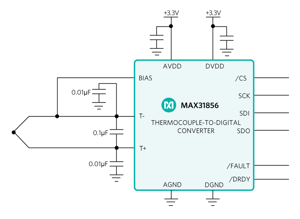
For higher frequencies, ferrite beads and differential filters can be used to reduce the noise coupled into thermocouple leads. Installing a 100nF differential capacitor between the positive and negative leads as close to the artificial cold junction helps to mitigate some noise caused in the thermocouple lines. In applications with higher noise levels, especially high-intensity RF fields, additional 10nf capacitors should be placed between each lead and ground.
Click image to enlarge
Figure 2. Thermocouple IC with filter capacitors on the thermocouple inputs.
In addition to minimizing noise from being introduced by the thermocouples lines, another type of noise that may appear in thermocouple measurements comes from power supply coupled noise. The effects of power supply noise can be minimized by placing a 0.1µF ceramic bypass capacitor as close to the DVDD and AVDD pins and GND as possible. This helps prevent spikes in power supply voltage from affecting the temperature conversions. Figure 2 shows a typical application circuit for the thermocouple sensing IC MAX31856 with filtering capacitors applied to the thermocouple inputs. Additionally, twisting the thermocouple wires when possible keeps capacitively coupled noise from appearing as a differential noise voltage term.
Linearization
As mentioned earlier, the Seebeck coefficient for any thermocouple type is dependent on the temperature of the thermocouple, which creates a non-linear transfer function of voltage to temperature. The National Institute of Standards and Technology (NIST) maintains a published database of voltage-to-temperature conversions used for calibrating and testing each thermocouple type. The database consists of several different conversion methods. One method is a voltage-to-temperature look-up table that maps a differential thermoelectric voltage to a temperature value over the entire temperature range for each thermocouple type (assuming the cold junction is at 0°C). The other method is a series of 9th or 10th order polynomial equations used to convert voltage-to-temperature or temperature-to-voltage.
In most applications, after a raw thermocouple voltage is digitized by an ADC, the ADC output code needs to be translated to a temperature reading by either using a look-up table or performing several floating-point calculations. Using a look-up table for a large temperature range consumes significant memory, whereas performing many floating-point calculations consumes a significant amount of processing power in low-cost microcontroller applications. The MAX31856 offers flexibility by allowing either type of conversion method. It features an internal look-up table that provides linearized and cold-junction compensated temperature readings, or the ability to read back raw ADC results for further processing and filtering in microcontroller firmware.
Summary
When using a thermocouple as a temperature measurement device, there are many factors to consider before high-accuracy readings are realized. When it comes to thermocouple construction and placement, the effects of noise, sheath conductivity, and thermal insulation of the hot junction must be properly addressed. Additionally, proper treatment of the corresponding thermoelectric voltage includes proper shielding, RF filtering, decoupling, and series resistance minimization of the thermocouple leads. Once the thermoelectric signal reaches a PCB or measurement device, accurate cold junction compensation, line frequency filtering, digitization, and translation from voltage-to-temperature are essential for reducing measurement errors. Thermocouple-to-digital converter ICs like the MAX31856 simplify the acquisition of highly accurate thermocouple readings by addressing all of the above concerns in a single IC.