Microchip's latest 11 kW Totem-Pole Demonstration Application deploys PFC and DAB topologies effectively
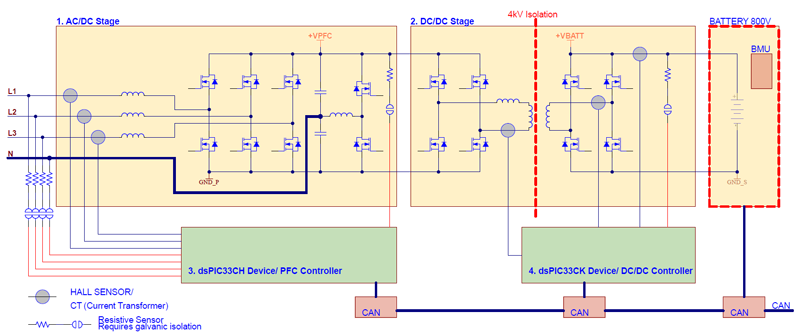
Figure 1: OBC Block Diagram
With its exceptional efficiency and capacity for bi-directional power transfer, the Totem-Pole topology offers a solution for integrating Power Factor Correction (PFC) and inverter functionality effectively. DC-DC topologies like the Dual Active Bridge (DAB) are well suited for battery chargers because of the high-voltage to current dynamics required and their bi-directional capability.
Building blocks shown in Figure 1
1. AC-DC, including Power Factor Correction (PFC) using totem-pole voltage doubler topology. It supports single-phase or three-phase operation, with output DC voltage (VPFC) greater than double the Vacmax- grid input voltage. This means that VPFC voltage is regulated to at least 750 V/800 V DC. This DC voltage is provided to the DC-DC follower stage.
2. DC-DC, as a downstream converter solution, here presented as DAB is providing galvanic isolation and voltage/current level scaling to a battery (VBATT) at the output. The output voltage demands vary from system to system, like 200 V- 400 VDC for legacy systems and 400 V-800 VDC for new systems. It is challenging to provide a solution, which supports all systems without performance and cost penalties. Which topology is optimal for this task has been a long discussion in the industry. Microchip is offering a DAB and a resonant CLLC platform.
3. dsPIC33CH dual-core Microchip device family is used as main controller at the PFC stage.
4. dsPIC33CK single-core Microchip device family is used as main controller at the DC-DC stage.
By using a distributed control architecture, the distributed systems use one controller per converter. The benefits of a distributed control architecture include:
1. The controller has the same reference ground as the signals that must be acquired. This enables low-cost current and voltage sensing, with high signal bandwidth and low noise.
2. The same controller can monitor auxiliary signals, which can improve system performance and reliability.
3. The control scheme can follow precise sequential timing and fixed latency, which is critical in digitally controlled systems.
4. Only digital signals like PWM must cross isolation barriers, which is more cost-effective than transferring analog signals.
Hardware Challenges
Specific technologies are required to realize such systems, for example, Silicon Carbide (SiC) FETs, used as the main switching element, enable a high switching frequency of 100 kHz and higher. This high voltage, high power Continuous Conduction Mode (CCM) operation was only possible because of SiC technology. Compared to silicon (Si) technology, SiC devices can handle greater than ten times the voltage capability of Si, enabling a thinner die that produces lower conduction and switching losses, as well as higher switching frequency and higher temperature operation.
1. Digital Signal Processors (DSPs): These devices have been on the market for decades and widely used in power supply applications.
2. Sensing circuitryis of very high importance in such systems, both for current and voltage. Very often the signals to be sensed are not at the same reference ground potential and therefore require galvanic isolation and/or signal level shifting. Transferring AC signals is much easier than DC signals. Isolated DC sensing requires active circuitries, offset voltage calibrations etc. For topologies like totem-pole PFC, , sensors must be bi-directional, provide high bandwidth and high dynamic range. - It needs to work as well at 100 mA as at 30A and must have low and constant propagation delays. The most popular sensors are Hall sensors followed by AnisotropicMagneto Resistive (AMR) sensors. All are inherently noisy at all current levels, due to internal amplifier and calibration circuitry.
Hall sensors can have up to 50mVpp noise in a very broad frequency range (including low kHz range). This is an issue when these signals are used as feedback for control loops. The noise gets amplified by the error amplifier thus injected in the plant loop. This gives us a random noise power amplifier. If the error amplifier has 10 dB gain in that kHz range, the controlled current will widely swing with amplitudes of up to 5A.
This noise is too powerful to be filtered at the power stage, it must be filtered at the source, by adding a low pass filter at the output of the sensor. Another option to reduce the control loop gain, which results in a lower system loop bandwidth. These issues can lead to degraded Total Harmonic Distortion (THD) or Power Factor (PF) performance, or resulting specifications not being met.

Click image to enlarge
In Figure 2 one can see the noise spectrum of two current sensors using different technologies: AMR has a broader frequency spectrum, but with a much lower noise level. In some cases, especially at lower frequency range of interest, the difference can be up to 20 dB.
Sensing Voltage Across the Galvanic Isolation
Sensing AC or DC voltage across the galvanic isolation can be a difficult and costly task. There are many challenges like linearity, DC offset stability or the need for an isolated bias supply. More solutions exist which claim to solve these issues. Unfortunately, such devices can be expensive. A digital solution can be simpler and cost effective than an analog solution.

Click image to enlarge
Microchip’s Isolated Voltage Acquisition Board can be used for isolated sensing of up to three voltages with the same reference ground potential. Three op amps, a small dsPIC33C and three digital optocouplers are used to scale, digitize, and transmit the sensed voltages across the isolation barrier.The whole board consumes typ. 50mA at 5V.
On the totem-pole platform, the inputs are connected to the three lines of AC mains. Every 10us, the 3x12-bit ADC readings of the 3-line voltages are sent from the board to the main controller via SPI. It has also a sync input, which allows the sampling instance to be synchronized to the PWM switching cycle.
The passive components of the circuit, such as flat-wire inductors, transformers for the gate-driver circuit and DC link capacitors, play an equally important role in terms of efficiency and reliability.
Flat Wire PFC Chokes
WE-TORPFC flat wire PFC chokes shown in Figure 4 are designed with a wide, flat cross-section, which minimizes core losses compared to traditional round wire chokes. This reduction in core losses translates to improved overall efficiency in power factor correction circuits.

Click image to enlarge
The flat geometry of the wire in PFC chokes facilitates better heat dissipation. This is particularly advantageous in high-power applications where managing heat is crucial.
The chokes can be wound more densely than traditional chokes, allowing for a more compact design.
In the design of the 11 KW totem-pole different constellations were made with different core materials and different wire types to achieve the best performance. A comparison of MPP and High Flux core materials based on permeability, saturation, AC core losses, and cost can be seen in Table 1.

Click image to enlarge
Push Pull Transformers for Gate Drive Circuitries
Galvanic decoupling using push-pull and gate drive transformers can help to prevent ground loops and the unwanted transfer of electrical energy between circuit blocks. In the topology mentioned, where high voltages and currents are prevalent, maintaining proper isolation while providing the lowest parasitic effects is the goal driving to complying with stringent industry standards.
Moreover, in electric vehicles, where batteries are a critical component, transformers provide isolation between the battery systems and consumer lower-voltage electronics.
Interwinding capacitance refers to the inherent capacitance between the windings of a transformer, and its importance in E-Mobility applications lies in its impact on the transient behaviour and high-frequency response of the transformer. As electric drivetrains demand faster switching speeds and higher frequencies, understanding and controlling interwinding capacitance become essential for optimizing the performance of transformers.
Excessive interwinding capacitance can lead to increased parasitic losses, higher power dissipation, and reduced efficiency in power electronics systems.
The new family of Würth Elektronik WE-PPTI and WE-AGDT offers all the above-mentioned benefits and optimization achieving interwinding capacitance below 1pF with an isolation voltage up to 4 KV AC, that makes the transformers perfect for being used in such applications.
DC-Link FILM Capacitor
WCAP-FTDB DC link capacitors are known for their longer lifespan compared to electrolytic capacitors. Electrolytic capacitors are prone to degradation over time due to factors like temperature, voltage stress, and the aging of electrolyte. DC link capacitors, often made with film or ceramic materials, exhibit better stability and reliability, making them suitable for applications where durability is a critical factor.
Electrolytic capacitors typically have higher equivalent series resistance ESR, which can result in power losses and decreased efficiency in power electronic systems. DC link capacitors, on the other hand, offer lower ESR, reducing energy losses and improving system efficiency.
DC link capacitors are designed to withstand a wide range of temperatures without significant performance degradation. This makes them suitable for applications in harsh environments or those subject to temperature fluctuations. Electrolytic capacitors may experience reduced performance or even failure under such conditions.
Electrolytic capacitors can be sensitive to elevated voltage stresses, leading to premature failure. DC link capacitors are less prone to failure under such conditions, making them a better choice for ON board chargers.