The drive towards more energy-efficient motor control in compressors and pumps
New energy efficiency standards and regulations put pressure on designers
Considering that almost 60 percent of total electric energy produced worldwide is used to run motors of every size, shape and efficiency, the adoption of variable speed drives can save as much as 70 percent of energy costs by controlling the speed of the load. New energy efficiency standards for compressors and pumps require the adoption of electronic controlled motors and present further challenges to electronic designers.
A high-voltage multichip solution based on standard QFN packaging technology such as IR’s µIPMTM product family has taken the same industry standard approach of VRM modules utilized in the computing industry into the industrial and motor-drives industry. By using PCB copper traces to dissipate heat from the module, a device of this kind delivers cost savings through a smaller package design, and in specific applications through eliminating the use of an external heat sink.
The implications of theERP Directive.
In Europe the key legislation that is driving the move to increasingly efficient fan and pump applications is Directive 2009/125/EC, or the European Energy Related Products (ERP) Directive. Designed to minimize energy consumption and support lower carbon emissions by improving energy efficiency, this legislation replaces the Energy Using Products (EUP) Directive and provides a framework for establishing minimum eco-design requirements for energy-using and energy-related products.
The Directive is implemented in the form of product-specific regulations that cover items ranging from finished units to sub-assembly elements of a finished unit, such as fans and circulator pumps. The Directive is being implemented in various stages, with the key dates for fans and circulator pumps being January 1st 2013 and January 1st 2015, as defined in regulations EU 327/2011 and EC 641/2009 respectively.
The impact of this new legislation should not be under-estimated. It has been estimated that between 30% and 50% of all fan and compressors currently in the market will not be compliant with the ERP requirements. By including the water pump circulators employed in heating and air conditioning systems, some expert has estimated that over 90% of those products currently on the market will soon be prohibited for sale. As a result, OEMs will have to replace their products with more energy-efficient systems if they are to achieve the all-important CE mark.
Facing this new demanding and challenging requirements, it is imperative for the power semiconductor industry to offer a simple and economical way to address the requests of designers for easy to use system in package solutions. These solutions must be also characterized by scalability in voltage and current range so to simplify standardization of assembly and portability of design.
Devices like the µIPM product family are intended to provide designers with an economical, flexible and scalable solution that it is easy to use across a fairly large range power level.
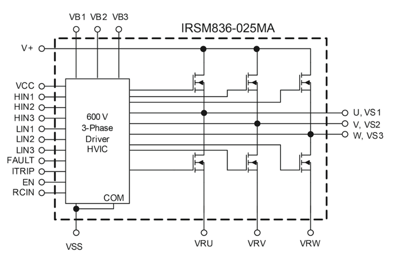
Features such as an open-source topology for leg-shunt current sensing help to further simplify motor control designs (common source options are also available) while optimized dV/dt characteristics minimize losses and the need for EMI trade-offs. The 3-phase µIPMs (see Figure 1) also incorporate propagation delay matching circuitry, ensuring that the response at the output to a signal at the input requires approximately the same time turn-on and turn-off time durations for both the low-side and the high-side channels.
Click image to enlarge
Figure 1: µIPM 3-Phase Inverter Internal Schematics
Despite their current and voltage ratings and high levels of integrated functionality, each of the new devices is supplied in a miniature ‘QFN-like’ package, which until now has been more commonly associated with low-voltage DC-DC controllers or voltage regulators. Indeed, with dimensions of just 12mm x 12mm x 0.9mm, the 3-Phase µIPM devices are believed to be the smallest IPMs currently on the market and can help designers to achieve space savings of up to 60% compared to alternative devices. This is without compromising isolation safety requirements, as the µIPMs meet the creepage distance requirements of the UL standards.
Among the factors that have led to these significant space savings is the approach taken to device cooling. In particular, unlike the poor die-to-PCB heat dissipation characteristics of gull-wing lead and DIP packages, the µIPMs achieve high die-to-PCB heat dissipation, allowing them to actively use the PCB as a heatsink. This is a similar approach that point-of-load (PoL) or VRM QFN-based packages use. The power semiconductors (500V FredFETs) and the HVIC die are bonded to the lead-frame, which is exposed and then soldered to the PCB.
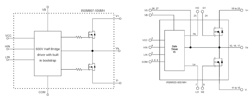
In order to address higher power level applications, the µIPMfamily has expanded with new 7mm x 8mm x 0.9mm and 8mm x 9mm x 0.9mm modules in Half Bridge configuration (see Figure 2) with voltage ratings including 40V and current rating capability increased to 10A for the 500V version and up to 30A for the 40V version.
Click image to enlarge
Figure 2. µIPM Half-Bridge Schematic and Pin-out versions
By splitting the integrated 3-phase inverter in 3 individual half-bridges, several benefits can be obtained. First and most importantly, this approach enables to spread the module power dissipation on a bigger printed circuit board area, improving the overall thermal performance.
In general, IPM current capability depends on the DC bus voltage, the ambient temperature, the switching frequency, and for all these elements, the higher they are, the higher the losses are), the modulation scheme (i.e. 3Phase vs. 2Phase), dV/dt of phase voltage and, of course, the FET characteristics (RDSON, IREC etc.)
In the case of a surface-mounted solution like the one offered by the µIPM™ family, the current capability also depends on the PCB design and specifically to the copper thickness, the copper pad areas, the number of layers and ultimately by the maximum allowable PCB temperature. In other words, the maximum junction temperature of the power semiconductors is, in fact, less of a concern than the maximum PCB temperature.
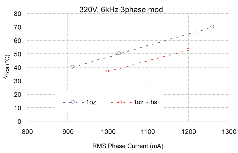
By increasing the PCB copper thickness the overall thermal resistance Junction to Ambient, is lowered and consequently, the PCB temperature. Lowering the temperature enables higher current capability. The following graphs (see Figure 3-5) illustrate the direct impact of the increased PCB copper and additional heath-spreader to the current capabilities of a 300W nominal compressor drive with the inverter stage based on 3 half-bridge modules IRSM807-105MH.
Click image to enlarge
Figure 3 µIPM 3xHalf-Bridge Inverter Phase Current vs. ΔTCA
Click image to enlarge
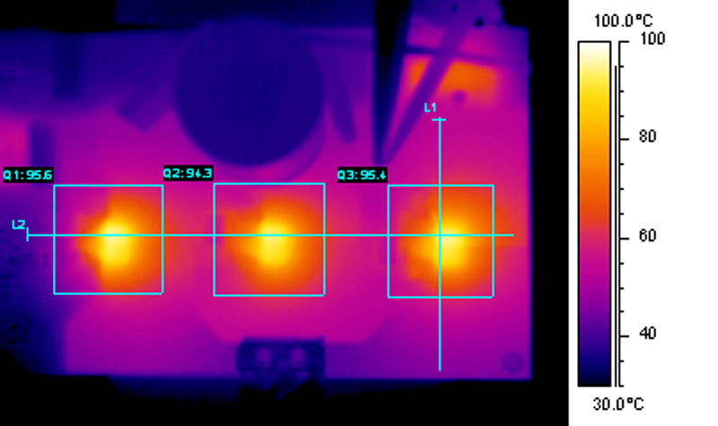
Figure 4 μIPM (HB) Thermal Image at Full Load
Click image to enlarge
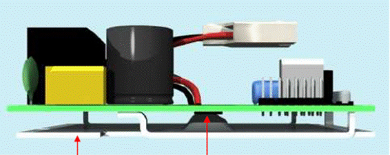
Figure.5 Compressor Drive Prototype
Output current capability increases with higher ΔTCA and also increases when a 2 phase modulation versus a 3 Phase modulation scheme is used. Similarly by lowering the switching frequency, lower switching losses enable higher output current. Additional top-mounted heat-spreader further reduces the temperature for even cooler operation. By using a set of µIPMs Half-Bridge modules, the overall compressor driver dimensions were also reduced to by 40% to a board 10cm x 7.7cm size.
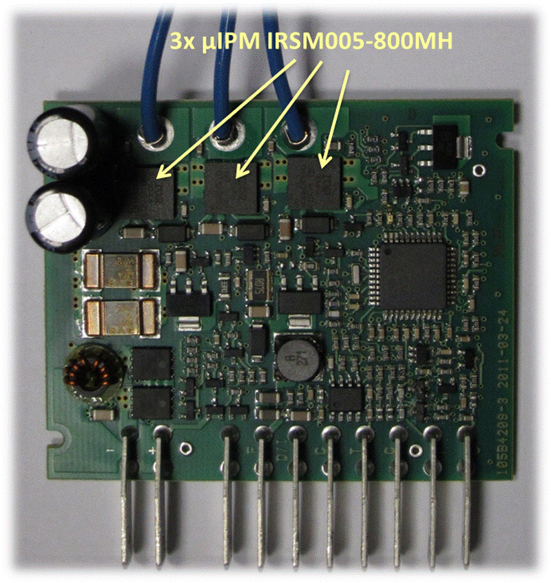
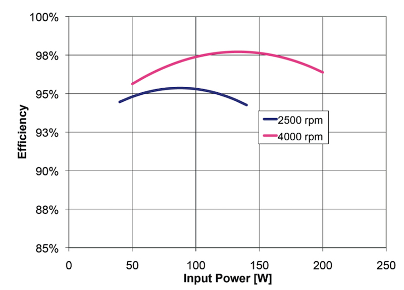
The µIPM family scalability come handy when higher current but lower operating voltages are required to address specific application. 40V-20A µIPM Half bridges been used to address high efficiency application on battery operated inverters for automotive applications. In this type of application, size and weight are paramount and the efficiency is a must. By using three Half-bridge µIPMs (see Figure 6) a complete 200W compressor operating at 5.5Khz with DC bus voltage range 10-32V has been realized is a minuscule heat-sink less 7cm x 6cm board. Efficiency up to 98% for the inverter was recorded at 4000 RPMs with maximum case temperature well below 85°C at the highest load profile (see Figure 7).

Click image to enlarge
Click image to enlarge
Figure 6 : µIPM Half-Bridge 40V-20A Inverter board
Click image to enlarge
Figure 7 : µIPM Inverter Efficiency Curve
Technology Trends
As much as a package platform is advanced, like the QFN based µIPM is, its thermal balance hence its current capability is ultimately defined by the power dissipation of the semiconductors used. Clearly all topologies based on Silicon switches have intrinsically limited improvement opportunities in term of power losses reduction and only by migrating to more advanced material it will be possible to achieve higher power density levels. Also based on state-of-the-art active components and passive components, constrained integration opportunities pose a limit to the technology evolution. For future integrated modules, GaN based switches have a better potential figure of merit than other power components based on Si or SiC material. The potential improvement achievable from GaN technology is significant based on the material limits.
To improve overall conversion efficiency, all inverter topologies require the power switch with the lowest possible specific RON*ETS Figure of Merit where RON is the specific On Resistance and ETS is the specific total energy per pulse loss. GaN-based MOSFETs show great potential in FOM improvement over the coming years.
The first generation of GaN based switch prototypes have 20x Lower Qrr compared to an IGBT Copak and more than 200x less than that of Super Junction body diode. Eoff (off switching loss) of these GaN Switches has been measured 72% less than for IGBT and 30% lower than HV Super Junction.
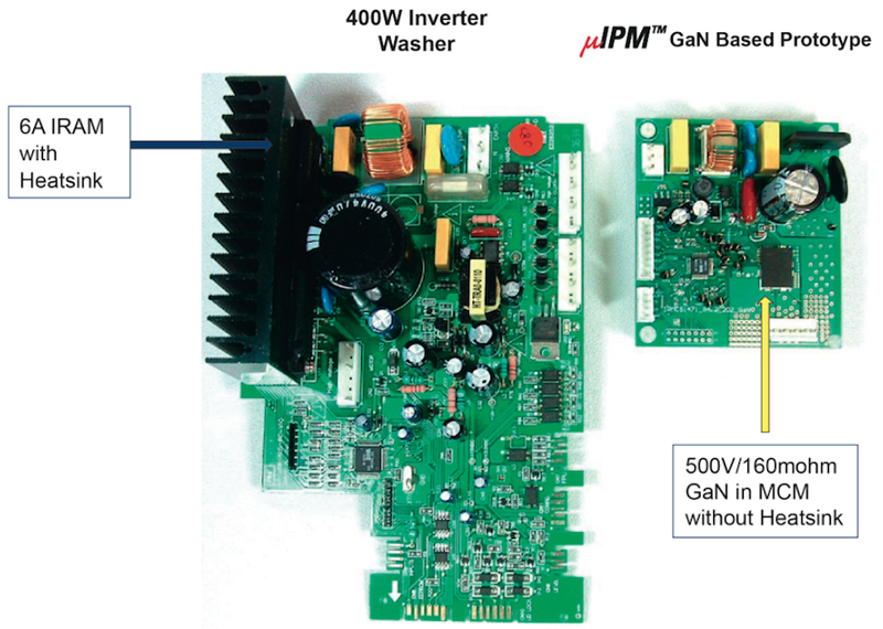
To prove in a real application all the above FOM improvements, a complete µIPM inverter stage, 12x15mm was built using prototypes of IR 500V Gan switches driven by a regular 3-Phase gate driver IC. The prototype µIPM Gan module with an IRMCK Digital control chip were the core of the small inverter board used for the power loss comparison. (see Figure 8). A standard home appliance inverter board using an IRAM IPM module was used as reference.
Click image to enlarge
Figure 8 Inverter boards comparison
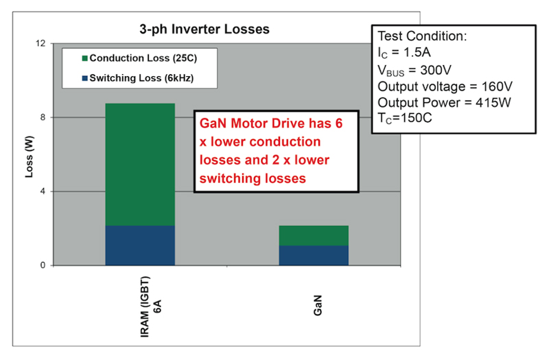
By loading both inverter boards with the same motor and loading profile (set by a dynamometer) the total power losses were compared (see Figure 9). GaN based µIPM module shown 6x lower conduction losses and 2x lower switching losses than the IGBT based module enabling the small inverter board to operate heat-sink less. Considering the overall power loss versus motor current, the Gan based µIPM has up to 4x total power loss reduction which translate to a 10x power density increase (module to module comparison).
Click image to enlarge
Figure 9a-b GaN µIPM prototype losses vs. IGBT based module