The Elegance of a Flyback Controller Without a Dedicated Isolated Feedback Path
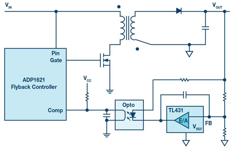
Figure 1: Conventional flyback controller with feedback path based on an optocoupler
Figure 1 shows the architecture of a conventional isolated flyback converter. These converters can be found frequently in power classes of up to about 60 W. A supply voltage is converted to an output voltage with the help of a primary-side switch and a transformer with adjusted turns ratio. Information about the output voltage is transferred via a feedback path to the primary-side PWM generator so that this output voltage can be kept as stable as possible. If the output voltage is too high or too low, the duty cycle of the PWM generator isadapted.
This type of feedback path costs money, takes up space on the board, and determines the maximum isolation voltage of the circuit together with the isolation voltage of the transformer. Optocouplers typically age, change their properties over time, and are usually not designed for temperatures above 85°C.
A better alternative is a substitute device that replaces the optocoupler and the secondary-side control module of the optocoupler. The ADuM3190 is available for this, with integrated iCoupler® isolation technology which transfers the feedback signals by inductive coupling — that is, without an optocoupler — across the galvanic isolation.
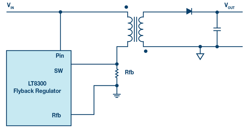
However, there is another option besides these. An especially elegant solution is to do away with a discrete feedback path completely. Figure 2 shows a flyback converter without a discrete feedback path. A suitable converter IC, the LT8300 from the Power by Linear™ group of Analog Devices shown in Figure 2, recognizes whether and how the duty cycle generated by the PWM generator must be adjusted by means of the voltage reflected back from the secondary side to the primary side. The advantage of this solution is that no optocoupler or other feedback circuit is required. This can save money and space. Any possible limiting influence of the maximum isolation voltage of the feedback path is then no longer relevant. As long as the transformer being used is designed for a certain isolation voltage, the complete circuit can be operated up to this maximum isolation voltage.
This concept is based on boundary mode regulation. Here, the secondary-side current drops to zero amps in every cycle. Then the output voltage, reflected back to the primary winding of the transformer, can be measured and used for the primary-side regulation.
Click image to enlarge
Figure 2: Flyback controllers without discrete feedback paths, but with regulation via the primary-side transformer winding
Whether this type of circuit, without a discrete feedback path, ispossible in a given application depends strongly on the required output voltage regulationaccuracy.Itcanbebetterthan±1%,butthedeviationcanalso be greater, depending on theapplication.
The output voltage can be calculated using the following formula:
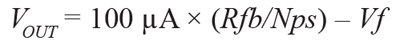
Rfb is shown in Figure 2. With it, the output voltage can be adjusted. Nps is the turns ratio of the transformer used, and Vf is the voltage drop across the secondary-side flyback diode. This is usually quite temperature-dependent. For output voltages set to high values such as 12 V or 24 V, the absolute effect of Vf is low. For a voltage of 3.3 V or even lower set at the output, the effect of temperature on the output voltage is quite high. Some no-optocoupler family members offer integrated temperature correction to make up for the different rectification diode voltage drops at different temperatures.
A minimum load at the output is also usually necessary for regulation to function properly. In the LT8300, it is approximately 0.5% of the maximum possible load.
Conclusion
Flyback controllers without discrete feedback paths, but with control via the primary-side transformer windings, make a simpler design without error-prone optocouplers possible.