
How More Power from PoE Helps Connect the World
Figure 1. Twisted pairs in an Ethernet cable powered by Power over Ethernet
Wireless technology continues to expand into more applications, delivering higher data rates, lower power and superior coverage. Wired Ethernet connections may seem like ancient technology sitting in the rear-view mirror beside fax machines, dialup modems and dot matrix printers. Yet Ethernet, with its low latency, dedicated bandwidth and power delivery capabilities, is actually one of the key building blocks for the infrastructure that will enable the wireless IoT to continue to expand.
New standards push Ethernet data speeds well beyond 10 gigabits per second, and the latest power over Ethernet (PoE) standard puts 90 watts of power over a standard 100-meter-long Ethernet cable. Created over a decade ago to power IP phones, the genius of PoE remains the same. PoE delivers power and data over a single, standard Ethernet cable that does not require any special installation permits or inspections.
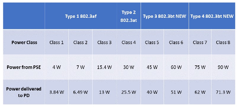
The initial IEEE PoE standard 802.3af ensured all PoE systems where interoperable and enabled Power Sourcing Equipment (PSE) to put 15 W of power onto the cable and deliver 13 W to the Powered Device (PD). The difference in power onto the cable and power off of the cable comes from losses within the Ethernet cable itself, which can be up to 100 m in length. The latest IEEE 802.3bt standard raises the maximum power to 90 W from the PSE and 71 W to the PD (see Table 1). All PoE standards are fully backwards compatible.
Click image to enlarge
Table 1 – IEEE 802.3 PoE Power Levels
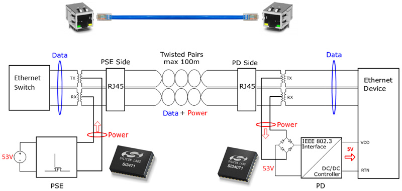
While the power levels have changed, the basic principles behind PoE haven’t. PoE injects between 48-57 V of common mode power onto the twisted pairs of an Ethernet cable using center taps added to the Ethernet transformers. The 48-57 V range reduces the current through the Ethernet cable while keeping the voltage low enough to comply with installation codes for Ethernet cabling. Depending on the PoE standard, either two or four of the twisted pairs are powered (see Figure 1).
All IEEE-compliant PDs, regardless of power level, are designed to take power from all four twisted pairs using an input bridge, as the original IEEE 802.3af standard allowed any two of the four pairs to be powered at any polarity. To ensure only PoE-enabled equipment is powered, the PSE only provides power if it detects a valid signature from the PD. After detection, the PSE and PD do an analog handshake called classification. The PoE standards divide power into different levels called classes. During classification, the PD requests a power class from the PSE, and the PSE either grants the PD the requested class or demotes it to a lower class. It is important for the PD system controller to check the assigned class and adjust the PD system power draw accordingly. Otherwise, the PD will draw more power than the PSE granted and will be disconnected.
A key challenge when implementing a PoE powered device is converting the ~50 V input to a voltage usable by the system, typically 12 or 5 V. Many PoE PD ICs now integrate a high-efficiency dc-dc controller and provide development boards for many common PoE PD dc-dc converters. (See Figure 2.) This single-chip solution allows designers to focus on the three key aspects of the PoE dc-dc supply: isolation, efficiency and electromagnetic interference (EMI).
Click image to enlarge
Figure 2. Two twisted pairs power PoE system
PoE operates on a safe, low voltage. However, if any metal in a connector or case is exposed to the end user, then isolation is required to protect the end user from accidental shock. In addition, if the PD system has any communication connector with a ground pin, such as USB or UART, isolation is needed. Developers should consult with a safety expert for general guidelines before making any decisions on isolation in a PoE-enabled system.
With the isolation decision made, the next consideration is the dc-dc power supply configuration, called the topology. Most non-isolated designs needing 13 W or less use a simple buck topology, which is inexpensive but cannot be isolated. Above 13 W of power, a flyback converter provides better efficiency and adds the option of isolation. Above 30 W of power, many system designers are using a forward converter to maximize efficiency.
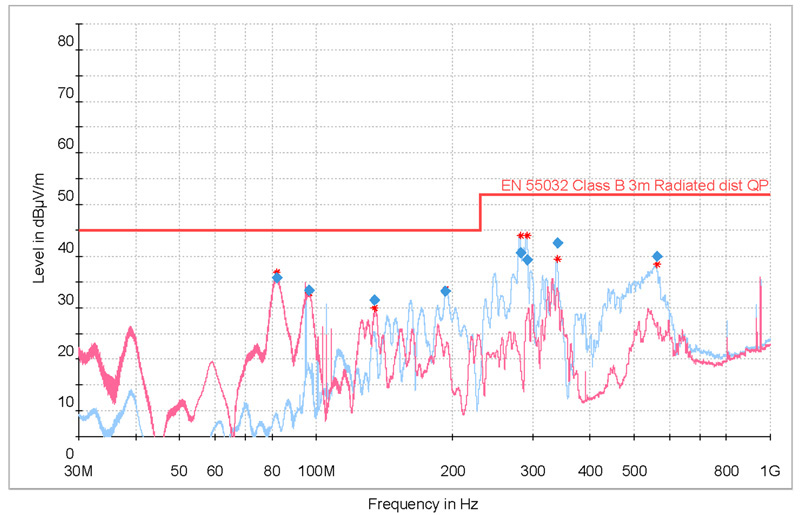
Finally, the dc-dc supply must pass stringent EMI requirements for the end product to be sold globally. This is one of the most challenging aspects of dc-dc power supply design, which involves a mixture of adjusting layout, adding snubber circuits and adjusting magnetics designs. The dc-dc controller integrated in many PoE ICs adds features to improve EMI performance, such as pulse width modulation (PWM) frequency spreading. With all of the choices, decisions and adjustments needed for a dc-dc converter, the easiest way for a new designer to get started is to leverage a reference design or evaluation board. Most PoE IC vendors provide multiple isolated and non-isolated designs that can be leveraged in an end system design. Some even provide an EMI test report for the design (see Figure 3), proving their PoE IC and converter design will pass EMI when properly adjusted. The dc-dc converter presents a key challenge for any PoE design. However, the latest PoE ICs, development boards and support material make this more accessible than ever.
Click image to enlarge
Figure 3. Radiated emissions test results for Silicon Labs’ Si34061 5V, 30W PoE EVB
Wireless connectivity represents the future of IoT, but Ethernet and PoE are also the backbone of that wireless future. Phones, tablets and laptops and many connected IoT devices need a wireless access point (WAP) to provide Wi-Fi connectivity. The access point in turn needs high-speed data and high power. A warehouse may have thousands of wireless asset trackers, but all the information from them must be collected and sent to a central server for processing.
An IoT gateway, with a dedicated PoE Ethernet connection, never needs a new battery and always has a reliable connection. Even the 5G revolution is turning to Ethernet and PoE to deliver improved connectivity inside buildings using small cells. The expanded power capabilities of PoE, coupled with faster Ethernet data speeds, will enable the wired infrastructure behind the IoT for many years to come.


