Demand for active PFC circuits in electric drives is on the rise
PFC circuits are finding their way into more and more electronic drives. Of course, the best choice of components will always depend on the given application - what's right for one may be wrong for another. And what's more, power semiconductors can also influence each other.
Demand for active PFC circuits in electric drives is on the rise. Regulations such as EN61000-3-2, more rigorous requirements for electro-magnetic compatibility, and the need for greater energy efficiency are driving this demand. Active PFC circuits also afford engineers the opportunity to source more power from the same power supply.
Fundamental selection criteria
Again, the choice of power semiconductor depends largely on the application and the engineering objectives as outlined above. Static and dynamic losses incurred during electrical conduction and switching vary from component to component. This variance is also contingent upon the load and switching frequency. The individual hardware components' properties have an impact. The ways in which they interact also factor into the loss equation, as a closer look at the boost diode's influence on losses at the boost switch reveals. Reverse recovery time (trr) is the period that elapses from the moment forward-flowing current is reversed to the point when the diode shuts off altogether.
Before that point is reached, some reverse recovery current (Irr) flows upstream; that is, against the forward current stop. As Figure 1 illustrates, this current, like the load current, then flows off from the boost switch. This generates added losses in the switch on top of the actual switching and conduction losses. These additional losses can be considerable, particularly in fast-switching MOSFETs used for high switching frequencies. In this scenario, a slow boost diode would have a major adverse effect on the losses incurred at the switch and thereby impede the switch's peak performance capability. In other words, a fast diode significantly improves the entire PFC circuit's efficiency. Losses may be reduced in multiples of ten percent, depending on the application.
Click image to enlarge
Figure 1: The load current (red) and the reverse current (yellow) flows right after the main switch shuts
Consideration must be given to the semiconductor's peak performance capability, which brings other key influencing factors into play. Static and dynamic losses, for example, also hingeon the temperature of the semiconductor. Its temperature, in turn, is determined to great extent by its thermal resistance. A semiconductor is usually mounted on a heatsink, the temperature of which can be deemed more or less constant, contingent upon its material and size. The size of the semiconductor and its interface to the heatsink determine precisely the amount of thermal resistance and therefore the temperature at specific losses. With the benefit of very good cooling, a semiconductor can achieve much higher performance.
As the preceding explanations would suggest, the calculations necessary to select the right components are anything but simple. This is why engineers appreciate the opportunity to simulate the application in advance. Manufacturers of power semiconductor components provide various means of doing this. Vincotech furnishes the integrated simulation environment flowISE, a simple way of testing the company's products with a range of application parameters. The following section looks at simulations of a few typical PFC applications to illustrate the problems of component selection outlined above.
Visualization by simulation
Vincotech has for years offered modules engineered specifically for PFC in drive applications. Modules labeled with the designation PIM+PFC contain all the power semiconductors required for these applications, including input rectifiers, PFC switches and diodes, and three-phase inverters. In addition, a ceramic capacitor is integrated into the intermediate circuit to improve the PFC circuit's switching behavior and EMC. There are now three generations of modules, each reflecting the next rung up the technology ladder for evolving semiconductors. A comparison of these modules' properties in different situations affords insight into the influencing factors described in the foregoing section.
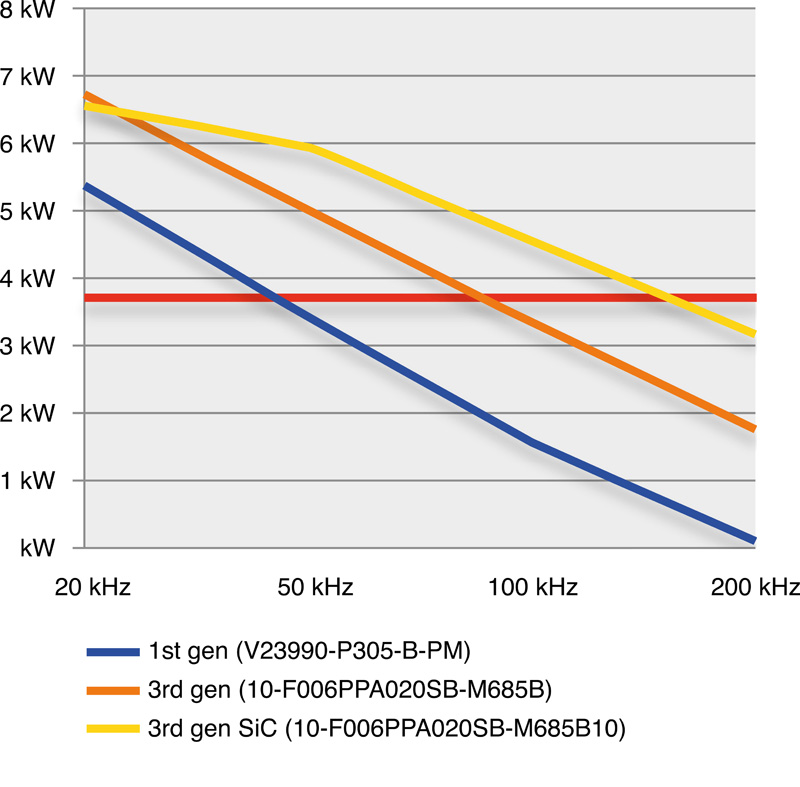
The first use case is a circuit in a 230 V power supply. The PFC circuit extracts sine-wave input current to provide conditioned power. This comparison shows a first-generation module (V23990-P305-B-PM) and two modules of the latest (third) generation (10-F006PPA020SB-M685B and 10-F006PPA020SB-M685B10 with SiC diode). The simulation clearly illustrates the advantages of the new semiconductor (see Figure 2). While the old module's ability to extract all the power available from a 16-A-fused line diminishes at a switching frequency of 50 kHz (230 V * 16 A = 3.68 kW, red line), the module with the SiC boost diode is able to continuing extracting full power up to nearly 200 kHz.

Click image to enlarge
Figure 2: Max output with a 230V input
The performance of the new module without the SiC is about midway between these two benchmark points. Note, though, that it is also significantly cheaper. The new module with standard components now costs just 85% of the V23990-P305-C-PM's original price, but there is a slight premium to be paid for SiC technology. The moderate price increase of 10% buys significantly higher performance and efficiency. At 50 kHz and given the theoretical maximum input power of 3.68 kW, the transistor and diode in the old module generate 53 W losses. Those in the new module with the standard technology generate 44 W, and those in the SiC diode just 33 W. Less energy is wasted when losses are lower, and cooling requires a lot less effort.
PFC circuits also serve another very important purpose: to significantly increase the intermediate circuit voltage in proportion to the line voltage. For one, this may be necessary to operate a device in countries with different mains voltages. This independence from the mains voltage has other benefits beyond that: Higher-voltage motors may be operated at lower coil currents to significantly increase efficiency.
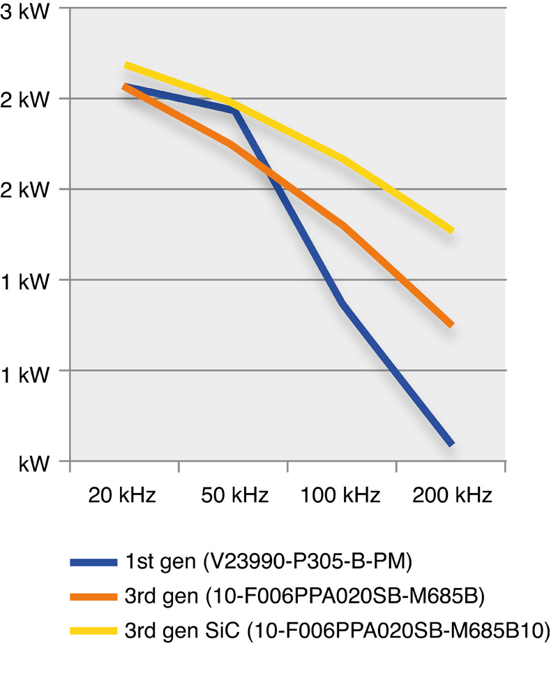
In addition, motors can always be run at their most favorable operating points. Voltage has been reduced to 110 V to simulate this use case, thereby resulting in a slightly different comparison (see Figure 3). While the latest-generation modules outperformed the old module in all previously studied cases, in this instance the older generation can keep pace with the younger, at least up to a switching frequency of 50 kHz. The old technology's powers only begin to wane significantly at higher frequencies.
Click image to enlarge
Figure 3: Max output with a 110V input
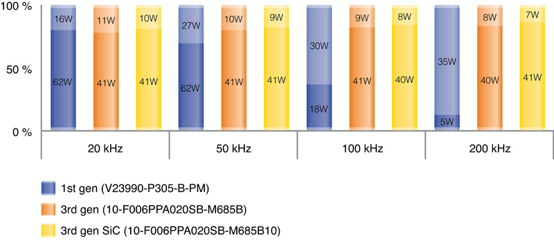
A closer look at the individual components' losses is necessary to get to the bottom of this. At low frequencies, the losses in the MOSFET dominate in all modules. This benefits the old module because the MOSFET has more than twice as much area and can therefore give off a lot more heat to the heatsink (61 W vs. 41 W). The drawbacks of the slow boost diode are apparent at higher switching frequencies, where it is pushed to the limits of its thermal load handling capacity.
A comparison of the two new modules reveals the key benefits of SiC technology. The MOSFET is clearly the limiting component for both modules over the entire frequency range examined here. However, each MOSFET reaches its peak capacity at different output power levels. This is attributable to the interaction between the boost diode and boost switch. The SiC diode shuts down much faster (13 ns vs. 46 ns) and has a significantly lower reverse recover charge Qrr (0.13 µC vs. 0.57 µC). The energy flowing from and through the diode during reverse recovery must flow through the MOSFET, where it generates higher losses. This explains why the module with the SiC diode is able to produce 40% higher output power at about the same losses. Figure 4 illustrates the MOSFET and diode's proportional share of losses.
Click image to enlarge
Figure 4: Losses by component at different switching frequenciesConclusion
Efficiency may be increased markedly with the benefit of ever more advanced semiconductors such as SiC diodes, fast IGBTs and MOSFETs with lower dynamic losses. These gains can be achieved with the same or lower costs for components. As the above examples have shown, the given application and the interaction among components have to be taken into account when choosing components. Good cooling also matters because it has such a decisive influence on the semiconductors' performance. Power modules are a very good solution because they allow for a simple, insulated interface and low-inductance connections among all other components, all of which helps achieve optimum electrical performance. Equipped with the right semiconductors, they can be used to create highly efficient systems with long lifespans at low overall cost.


