Understanding Transformer Diagnostics
Since the 1960s, the electric power industry has developed, refined and relied upon dissolved gas-in-oil analysis (DGA) to diagnose the degradation of insulating materials inside liquid-filled transformers. Dissolved gas concentrations are routinely measured by drawing oil samples from the transformer, extracting the gases in a controlled manner, and quantifying them using laboratory gas chromatography. Increasingly, gas monitors installed on transformers are performing these measurements in real time.
DGA is sensitive to a wide range of possible transformer problems, even in their early stages of development. Moreover, current DGA interpretation techniques provide insight as to the nature of the problem and the urgency for further investigations or corrective actions. These powerful capabilities for early fault detection and prioritization enable asset managers to make timely and informed decisions to minimize the financial downsides associated with transformer faults.
Gases Critical to Changes in Asset Condition
DGA interpretation commonly begins by examining the rate of combustible gas formation, which increases as the fault condition deteriorates. Next, the relative composition of gases provides a means for detecting changes in fault condition. For example, as a fault in oil increases in temperature, the relative composition will change from predominately methane and ethane to higher amounts of ethylene. If the fault temperature rises enough, acetylene will begin to form. When this happens, the increased fault temperatures around cellulosic paper insulation will often speed up the generation of carbon oxide gases, decreasing the carbon dioxide/carbon monoxide ratio. An asset manager may choose to continue operating the transformer with a low temperature fault in oil, possibly increasing the DGA sampling rate or installing an on-line DGA monitor. On the other hand, a unit exhibiting a high temperature fault in oil would likely be taken out of service more quickly.
Click image to enlarge
Figure 2
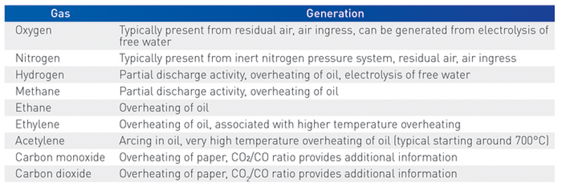
The gases most commonly used for DGA are given in Table 1 along with an indication of the conditions under which they are formed.
Table 1. Gases of Interest
Click image to enlarge
Individual gas concentrations
Large populations of transformers have been analyzed to determine statistically normal amounts of each dissolved gas in operating transformers. By comparing one transformer against the resulting 90, 95, and 99 percent norms, it is possible to characterize gas concentrations that stand out from typical behavior. However, an “abnormal” gas concentration does not necessarily indicate a serious problem. Circumstances such as loading, ambient conditions, or system events can lead to excessive gassing compared to statistically normal values. Higher gassing rates can temporarily occur during the “breaking in” period, when new or recently processed transformers are energized and loaded. Some transformer designs have non-critical gassing that exceeds that of the norms but fits a consistent pattern for that design. For these reasons, gas concentrations exceeding the percent norms should be considered as a warning that an issue could be present and that further information should be gathered, such as increased DGA sampling and interpretation, complementary electrical testing, and/or on-line monitoring.
Acetylene
Acetylene stands out from the rest as being important at any detectable concentration. In the progression of a thermal fault, this critical gas is formed only at the more extreme temperatures, starting with localized overheating above 700°C. In such cases, the acetylene concentration is typically less than 10% of the ethylene concentration. When the acetylene makes up a higher proportion of the hydrocarbon gases, a critical arcing fault is likely present. The statistics suggest a normal concentration is <5 ppm, which includes the contribution of non-critical thermal faults in aged transformers. However, even 1 ppm of acetylene would be considered a possible serious indicator if found in a new transformer, or when first observed during the service life.
Gassing rate
Typical gassing rates have been evaluated based on DGA measurements on large numbers of operating transformers. One way of characterizing the rate is to monitor the total combustible gases which include: hydrogen, methane, ethane, ethylene, acetylene and carbon monoxide. As fault conditions deteriorate, the gassing rate increases and can be used as an indicator for urgency of response. On-line monitoring can be used to quickly detect changing gassing rates and determine how gassing varies with operating temperature and load. Some problems are voltage dependent while others more closely track the load. In extreme cases, loading can be reduced for a period of time to limit the deterioration rate until a planned outage, rather than interrupting service under emergency conditions.
Gassing pattern
The relative concentrations of gases are used to determine sources of gassing and the type of fault condition. Importantly, the gassing pattern can often be used to determine if the fault is in the oil or the solid insulation. If in the oil, the gases will primarily be hydrogen, methane, ethane, ethylene or acetylene. Overheating of the cellulosic paper insulation will result in the formation of carbon oxide gases.
The gassing pattern can further provide some information about the temperature of the fault condition. Greater amounts of ethylene and the presence of acetylene are indicators that overheating in the oil is at higher temperatures. Quantitative methods have been developed and improved over the years to classify fault types using ratios of gas concentrations. These include the key gases, ratio tables, and Duval triangles and pentagons.
Carbon oxide gases
The carbon oxide gases are primarily formed through the breakdown of the cellulosic insulation. The rate of formation of carbon oxide gases and their relative composition are influenced by the amount of paper in the fault region, the temperature of the insulation in this region, the background amount of carbon oxide gases from the global degradation of the insulation system, and the amount of oil in the transformer. Shell form transformer designs have significantly lower oil/paper mass ratios than core form transformers and therefore can have higher concentrations of carbon oxides, particularly carbon dioxide. The transformer design must therefore be considered in determining what concentrations of carbon oxides are normal.
Carbon oxides can also be generated from the insulating oil and other components particularly when the oxygen content is high. Carbon monoxide may be preferentially lost from the oil over time, especially for gas blanketed and air breathing transformers. For these and other reasons, tests for furans, methanol and ethanol are also useful to assess the condition of the solid insulation. For localized overheating, the carbon oxides generally give better information, while for long-term aging, furans and the alcohols can provide confirming and complementary information.
Oxygen and Nitrogen
Oxygen and nitrogen will always be present but the amounts will vary with the oil preservation/expansion system, if the oil was recently degassed, and depending on presence of leaks in sealed systems. High nitrogen can be an indicator of incomplete degassing, air ingress or, in extreme cases, overpressure in a gas blanketing system.
The oxygen content will be determined by the difference between residual oxygen and ingress from air on one hand, versus oxidation reactions consuming oxygen on the other. High oxygen content can increase the rate of formation of some of the measured gases.
On-line DGA Monitoring
DGA monitors provide updated dissolved gas readings every few hours, enabling automated, early detection of a wide range of incipient faults. The influence of loading and temperature on gassing (and moisture) behavior can also be studied on the timescale of hours. Increasingly, DGA monitor data is processed on-the-fly using the DGA diagnostic methods described above (levels, trends, and ratio methods) to determine fault conditions and prioritize the need for intervention. This approach requires that the DGA monitor readings have sensitivity and accuracy on par with a good DGA lab. Accurate and robust DGA monitors using gas chromatography have been developed for this purpose.
Other tests and sources of information
We have described how DGA can detect a wide range of transformer problems and reveal changes in fault conditions as they evolve. However, other information is generally required to complete the picture of transformer health and confirm the root cause of any problems. On-line and off-line electrical and other tests complement DGA methods, as do comprehensive oil quality tests, and a review of the maintenance history. Together these methods allow asset managers to make informed decisions regarding operations, maintenance and investments needed to sustain a reliable and cost-effective electrical grid.