Many analog circuits need a type of clock signal for a possibility of executing a task after a certain time
There are various solutions available for timing applications. For simple tasks, a standard 555 circuit can be used. With the 555 circuit and the appropriate external components, numerous different tasks can be performed.
One disadvantage of the popular 555 timer, however, is the inaccuracy of the timer setting. A 555 timer works through charging an external capacitor and detecting a voltage threshold. This circuit is very easy to create, but its accuracy depends strongly on the actual value of its capacitor.
Crystal oscillators lend themselves well to applications requiring higher accuracies. Their accuracy may be high, but they show weakness in another area: reliability. Anybody involved in repairing electrical equipment knows that failure is usually caused by large, predominantly electrolytic capacitors. Crystal oscillators represent the second most frequent cause of failure.
The third way of measuring lengths of time or generating clock signals is with a simple, small microcontroller. Here, too, there is a large selection of components with different optimizations available. However, they need to be programmed, their handling requires a somewhat more in-depth understanding, and they must be scrutinized carefully in critical applications due to their digital design—for example, what occurs in the system if the microcontroller gets stuck.
Apart from these three basic building blocks for clock generation, there are other, less well-known alternatives. The TimerBlox modules from Analog Devices constitute one such alternative. They are silicon-based timing modules that, unlike microcontrollers, are fully analog in operation and can be adjusted via resistors. Thus, software programming is not necessaryand the function is very reliable. Figure 1 shows an overview of the different TimerBlox modules with their respective basic functions. Countless otherfunctions can be generated with these basic building blocks.
In contrast to the widely used 555 timer circuits, the TimerBlox circuits do not depend on the charging of an external capacitor. All settings are made with resistors and the function is therefore more precise. Accuracies of 1%to 2% can be realized. Crystal oscillators have an even higher accuracy of about a factor of 100, but this comes with the disadvantages such a solution brings.
Click image to enlarge
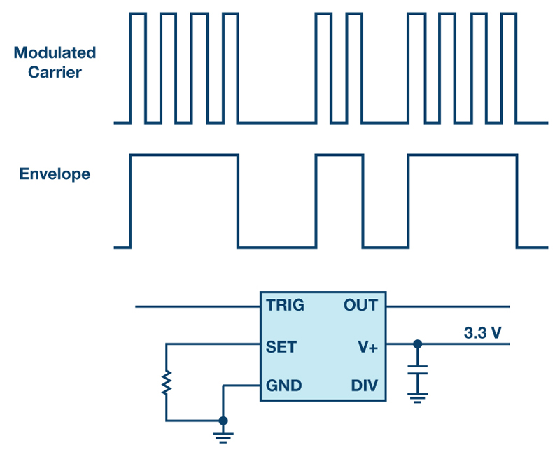
Figure 2. Envelope detector with an LTC6993 TimerBlox integrated circuit.
The applications for timing blocks are very diverse. Numerous example circuits have been published by Analog Devices. Figure 2 shows an envelope detector. Several fast pulses are combined to form a longer pulse. The external components of the LTC6993-2 are minimal for this application. The capacitor in the circuit is just a backup capacitor for supporting the supply voltage and has no effect on the accuracy of the timing module.
Other interesting applications include phase-shifted synchronization of multiple switching regulators for power supplies or the addition of spread spectrum modulation to a switching regulator IC with synchronization input. Another typical application is the provision of a defined delay, that is, the function of a timer for switch-on delays for specific circuit segments.
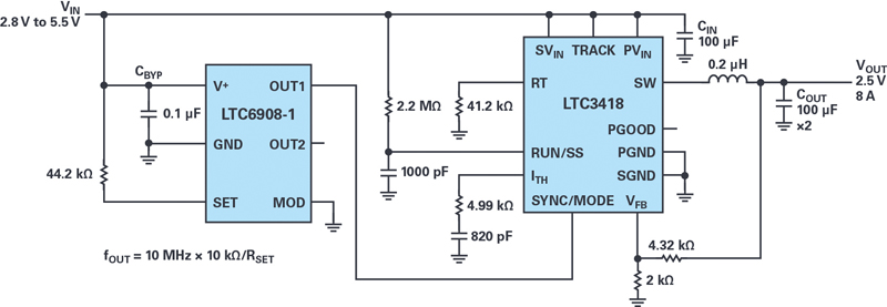
Let us look at an example of spread spectrum modulation for switch mode power supplies. Figure 3 shows a circuit with the LTC6908-1. It can attach to a switching regulator’s synchronization pin and cause a power supply to do spread spectrum frequency modulation (SSFM). Such a setup will make a switch mode power supply not switch at one fixed switching frequency, but it will then switch at varying frequencies to avoid excessive EMI noise at one particular frequency. SSFM is popular in some designs, where it is key to pass certain EMI specifications. While this concept can be effective, be aware, that the generated EMI is still there, it is just spread onto different frequencies.
Some switching regulators offer SSFM function but very many do not. A device like the LTC6908-1 can be attached to a synchronization pin of a switch mode power supply and the power supply will operate in SSFM. Figure 3 shows such a set-up with the LTC6908-1 adding the frequency modulation to the LTC3418 step down DC/DC converter. The LTC6908-1 has two outputs. They are 180 degrees out of phase. This can be used if multiple power supplies are running in one system and besides SSFM, a phase shift is needed to reduce the pulsed input currents of a buck (step-down) topology. If even more power supplies need to be synchronized, the LTC6908-2 offers a 90 degrees phase shift on its second output line.
The Cbyp capacitor connected to the V+ pin is only bypassing and is not setting any timing behavior of the device. So the exact value of this capacitor is not critical for system performance. The resistor between the supply voltage and the SET pin is the component which sets the oscillator frequency. With a precision resistor on that pin, we achieve smaller than 1.5% frequency error.
The SSFM is set to a range of +-10%. Within that range, the modulating waveform is a pseudo random waveform. It is generated by a linear feedback shift register that is 15 bits long. This sequence will repeat every 32767 * N clock cycles and gives a repetition rate below 20Hz for output frequencies up to 10MHz.
Click image to enlarge
Figure 3. Example circuit with a LTC6908-1 adding Spread Spectrum Frequency Modulation to a power supply
There are numerous different technical solutions for generating a clock signal and performing various time-based tasks. Each of them has advantages and disadvantages. Silicon oscillators such as the TimerBlox modules are characterized by ease of operation, high accuracy due to the use of variable resistors instead of capacitors, and excellent reliability.
Analog Devices