The Role of IGBTs in Increasing Motor Drive Efficiency
With the increased focus on operational efficiency of electric motors for all applications, the need for high efficiency drives is becoming more important
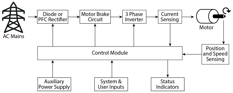
Figure 1: Illustrates a typical motor drive design that has a Power Factor Correction (PFC) input rectifier
Designs using motor drives, such as for electric vehicles, pumps, and fans, are being pushed to reduce the overall costs as well as decrease energy consumption in these same electric motor applications. Therefore, the selection of highly efficient devices for electric motors and their drives, and making sure each device is suited to the specifications of the particular application becomes even more critical.
Widely-known as a proven switching device solution, Insulated Gate Bipolar Transistors (IGBTs) meet the higher voltage/higher current and low frequency requirements in motor drive applications. Since these motors need to maximize efficiency and many times require a robust Safe Operating Area (SOA) and short circuit rating, IGBTs with co-packaged Fast-recovery diodes (FRD) are recommended.
This article outlines the advantages IGBTs bring to a motor drive design. In particular, it presents how performance and efficiency targets, and current-handling and peak voltage rating affect the selection of IGBTs and the importance of understanding short circuit withstand times.
IGBTs in Motor Drive Design
Motor drive designs typically use power from the AC mains and apply it to the electric motor according to user inputs (Figure 1). A power-factor-correcting rectifier is made using IGBTs, similar to what is used in an Uninterruptable Power Supply (UPS). The motor brake circuit is comprised of IGBTs that dissipate power from the motor or is used to route excess energy back to the AC input when it stops to accomplish regenerative braking. At the specified voltage and frequency, the motor drive inverter changes the DC voltage energy stored in capacitors to AC waveforms in order to control the motor at the desired speed and torque.
To maintain an IGBT below its SOA rating in the various sections of a motor drive design, heat must be removed from the transistor package. For this reason, designers should evaluate IGBTs housed in smaller packages that feature enhanced thermal dissipation. For example, IGBTs are available in a thermally efficient TO-247 package with the ability to provide effective heat dissipation for the power loss due to switching transients and forward conduction in the IGBT and FRD. In a motor control application, designers need to consider the system-wide impact of power dissipation, where ambient temperatures are high, and there is less or no airflow. And, designing with IGBTs that have been optimized for high efficiency means they produce less heat that needs to be dissipated. Other benefits of reducing the size of the IGBT include lower costs, as well as the ability to simplify the thermal management design.
Switching and Conduction Performance
The device structure of an IGBT determines its efficiency and performance. Advanced IGBTs that have an asymmetric structure help to heighten on-state losses and switching speed in motor control applications. The key attribute of this structure is the field-stop layer created by an n+ type buffer region that is added beneath the n- drift region and above the lower p-doped layer. The inclusion of this buffer region supports the electrical field and permits a thinner n- drift region, which in turn, helps to significantly decrease conduction losses.
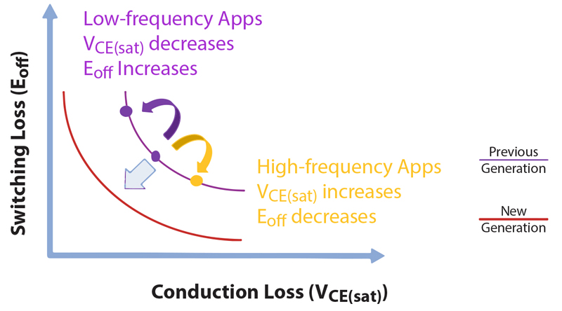
The overall compromise between switching losses (Eoff) and conduction losses (VCE(sat)) is shown in Figure 2. This illustrates why understanding low frequency versus high frequency system requirements is necessary in order to specify the proper IGBT device solution. In many new applications, IGBTs that use advanced Trench-Gate Field-Stop (TGFS) technology offer increased cell density that enables them to provide higher VCE(sat)/Eoff curve performance.
Click image to enlarge
Figure 2: Shows the trade-off of switching loss (Eoff) and conduction loss (VCE(sat)). Enhanced VCE(sat)/Eoff curve performance is achieved with IGBTs that integrate advanced TGFS technology, such as the Bourns IGBT discrete BID series
Short Circuit in Motor Control Applications
Motor control applications that operate in harsh conditions many times place high stresses on IGBTs that lead to transient short circuit conditions. These conditions can also cause an IGBT switch to experience a short circuit path from the DC voltage bus to ground (as shoot-through current) or across one motor phase to another phase or to earth. Therefore, the selected IGBT must be able to withstand these failures based on the end application’s required time interval to detect them. Motors are generally capable of absorbing very high current levels for relatively long periods (milliseconds to seconds); however, IGBTs typically specified in motor drive inverters have very short (microsecond) circuit withstand times. To mitigate this issue, suppliers such as Bourns have designed particular IGBT models with a short circuit withstand capability of 10 µs.
A benefit from IGBTs that offer increased short circuit current levels and reduced short circuit withstand times in the 5 µs range, is the trade-off for lower conduction loss that can also aid in decreasing overall BOM costs. Luckily for motor control designs some of the differences in short circuit withstand time can be made up by IGBT technology advancements. For instance, some of the latest IGBTs offer higher transconductance and lower thermal resistance that result in lower conduction loss and higher efficiency. These benefits can even be achieved from an IGBT that features a reduced short circuit withstand time.
Evaluating IGBT Trade-offs
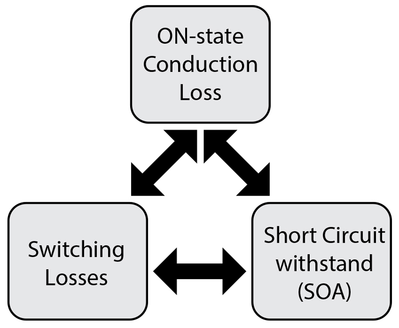
Choosing an IGBT device that features high switching frequencies through lower switching losses will bring about higher conduction losses. And, higher conduction losses cause higher power dissipation that requires a larger and bulky heatsink. This results in increasing the overall system cost and adds undesired space to the design. Conversely, an IGBT device with lower conduction losses operates efficiently at lower frequencies, but its short circuit withstand capability is decreased. This trade-off is illustrated in Figure 3.
Click image to enlarge
Figure 3: Motor control design trade-offs of conduction loss, switching loss, and short circuit withstand capability with reference to the associated Safe Operating Area
Safe Operating Area (SOA) Considerations
IGBTs that are selected to operate near their current and voltage maximums require careful consideration in how to safely keep those parameters within data sheet specifications. The primary concern should be to keep the collector current below the maximum, and at the same time, hold the voltage from collector to emitter below the data sheet value.
When operating in the forward biased condition in the Forward Bias Safe Operating Area (FBSOA), maximum pulsed collector current specification is met based on the pulse width and the impedance of the thermal design. The FBSOA defines the maximum saturated collector current for the maximum collector-emitter voltage, which is usually used for inductive loads. In the reverse-biased condition in the Reverse Bias Safe Operating Area (RBSOA), the maximum current is a function of the peak voltage between collector and emitter during turn-off. Adhering to maximum limits is necessary to protect the fast recovery diode (FRD) at the maximum junction temperature.
Conclusion
Because of their smaller die size that enables a higher current density design, specifying IGBTs for inverters in electric motor control applications allows designers to meet lower system cost targets. In addition, designers need to look for advanced discrete IGBTs that have the features necessary to support higher temperature operation and provide the enhanced ability to dissipate heat from IGBT packages. These newer devices, including Bourns’ latest Model BIDx IGBT series, offer a thermally-efficient design that combines the benefits of lower operational loss along with greater overload and higher short circuit current withstand capabilities. The result is a significantly enhanced switching solution for motor control applications.
As previously presented, optimization is required to balance the IGBT between conduction losses and switching losses. It is also important to tune for a specific application requirement based on the type of motor used in the end application. For most motor control applications, an IGBT that is 600 V/650 V-rated with Trench-Gate Field-Stop (TGFS) technology and co-packaged FRD in a compact TO-247 package is considered the ideal device solution. When sourcing IGBTs, these device features provide heightened thermal performance, low VCE(sat), and offer high efficiency due to lower total power dissipation, all while delivering high reliability as compared to previous generation planar IGBTs.