The SIMO DC-DC Converter - The Audio Amplifier's Best Friend

Learn how SIMO regulators can help with the overall design of audio devices by restraining output voltage ripple with programmable peak current limit.
Figure 1. Small wireless audio devices have challenging size and battery life requirements and are expected to provide excellent audio performance.
Generally, traditional switch mode power supplies (SMPS) are considered to be very noisy compared to that of the low-dropout (LDO) regulators. The switching action associated with switching regulators generates noise and resulting harmonics, which can affect the overall system performance in audio applications. Thus, using SMPS for audio circuits presents design challenges. Although a filter or an LDO placed after a switcher may dampen the switching noise, the cost from the extra components, the increased solution size, and the decreased system efficiency are undesirable for the electronics manufacturers and the end consumers. In addition, small wireless audio devices have challenging size and battery life demands (Figure 1). A careful balance is required to achieve an optimal solution.
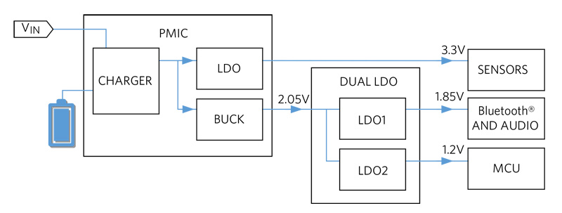
Figure 2 shows the typical power flow of a hearable audio device where LDOs are adopted for driving the noise sensitive components.
Because of the heavy use of LDOs, the associated lower efficiency causes significant heat dissipation and shortens battery life, thereby degrading user experience. With SIMO products, higher power efficiency can now be achieved while meeting the low-noise specifications of the toughest audio devices with minimal BOM addition.
Click image to enlarge
Figure 2. Typical power flow diagram of hearable devices
As discussed herein, an ideal and innovative solution is a single-inductor multiple-output (SIMO) buck-boost regulator which implements three buck-boost regulators that share a single inductor. It drastically reduces the solution size while still providing high efficiency. Meanwhile, the programmable peak current limit allows adjustment of the output voltage ripple either in the factory or on the fly to meet the strict system requirements of sensitive audio amplifiers.
How SIMO Works
Click image to enlarge
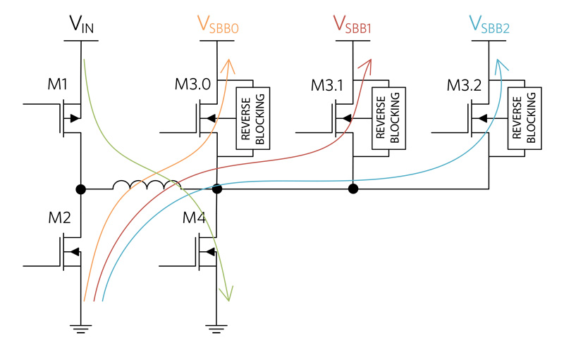
Figure 3. Simplified diagram of SIMO in buck-boost mode
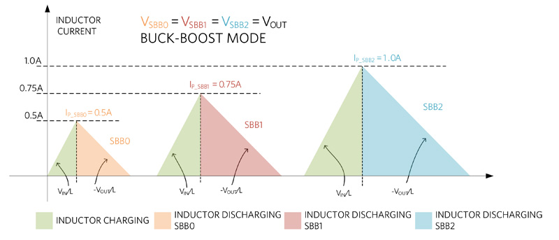
Figure 3 shows the simplified diagram of the SIMO topology. An illustration of the inductor current waveform of the SIMO operation is shown in Figure 4. The SIMO adopts discontinuous current-control mode. In the MAX77654 SIMO, it can operate in buck or buck-boost mode to support the wide output range from 0.8V to 5.5V. In buck-boost mode, for example, the inductor starts a cycle by building up current with M1 and M4 “ON” at the rate of VIN/L. When it reaches the corresponding peak inductor current limit programmed for the output rail being serviced, the current is subsequently delivered to that rail through the M2 and M3.x transistors.
Click image to enlarge
Figure 4. Simplified diagram of SIMO
More information is provided in technical overview articles that describe the operation of this innovative architecture, such as Application Note 6601and Application Note 6628, if you would like to delve deeper.
Output Voltage Ripple
For switching regulators operating under discontinuous conduction mode (DCM), it is widely assumed that the large inductor current ripple in DCM creates large output voltage ripple, which is detrimental to noise sensitive applications. Fortunately, the programmable peak current limit of the SIMO restrains the inductor peak current and thereby reduces the induced output voltage ripple. Combined with the knowledge that low-load currents are common in ultra-portable applications, the peak current limit of each output rail of the SIMO can be either pre-programmed or adjusted to an optimized value to achieve lower output voltage ripple without compromising the output power.
As illustrated in Figure 4, the peak current limit bounds the inductor current ripple. With the same load condition and operation mode (buck/buck-boost mode), a lower peak current limit essentially reduces the amount of energy transferred to the output for each switching cycle of a specific output rail. This leads to an increased switching frequency for the rail and reduces the output voltage ripple.
Click image to enlarge
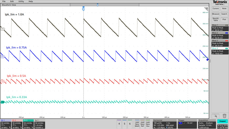
Figure 5. Simplified diagram of SIMO
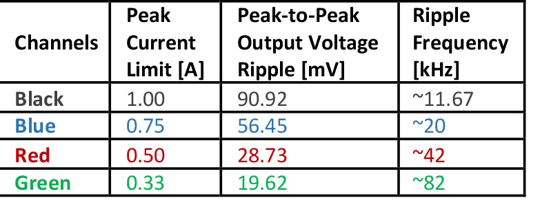
There are four peak current limit options in the MAX77654 SIMO: 0.33A, 0.5A, 0.75A, and 1A. The peak current limit can be independently programmed for each output. Figure 5 shows SIMO output voltage ripples by applying the same application conditions to a single channel with a different programmed peak current limit: 3.7V input voltage; 1.8V output voltage; 1.5µH inductor; 22µF output capacitor; 10mA load current. The significant impact of the peak current limit on the output voltage ripple can clearly be observed from the scope shot in Figure 5 and the data in Table 1. With the peak current limit at 0.33A, the peak-to-peak output voltage ripple can get lower than 20mV.
Spectral Performance with CODEC
To demonstrate the superior performance of the SIMO PMICs for audio applications, spectral tests were conducted with the SIMO and a high-performance audio headphone amplifier. The test configuration and the in-band FFT results are shown in Figures 6 and 7.
Since Maxim’s innovative SIMO architecture operates in DCM mode, interference between channels naturally spreads out the switching frequency spectrum and results in the reduced likelihood of injecting a strong carrier when there is a signal on another channel.
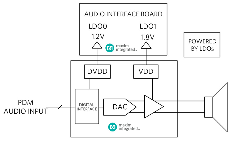
Figure 6(a) shows the setup of an audio amplifier with DVDD and VDD powered by two discrete LDOs on an audio interface board; in comparison, the same audio amplifier with DVDD and VDD powered by two of the three SIMO output rails of SIMO is shown in Figure 7(a). The load, illustrated by a speaker icon, was implemented with a 32Ω resistor in series with a 15µH inductor.
Click image to enlarge
Table 1. Output Voltage Ripple Measurements with Different Peak Current Limit Settings
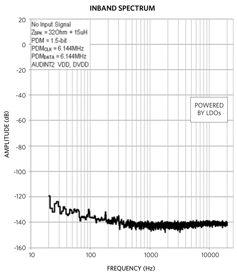
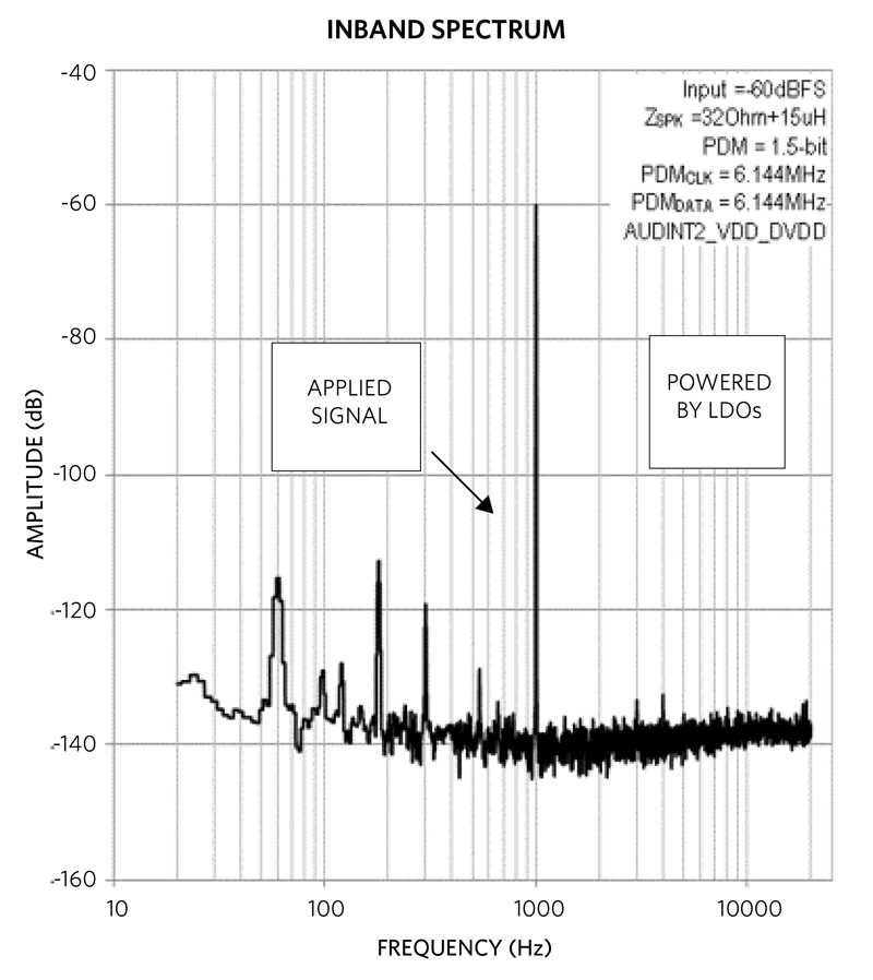
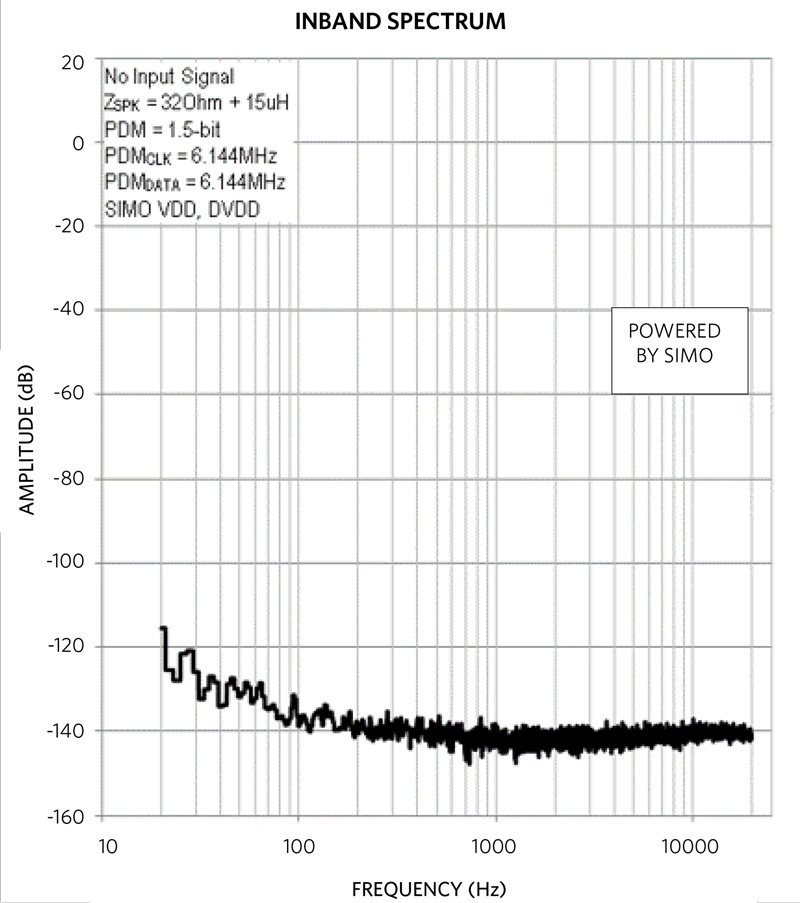
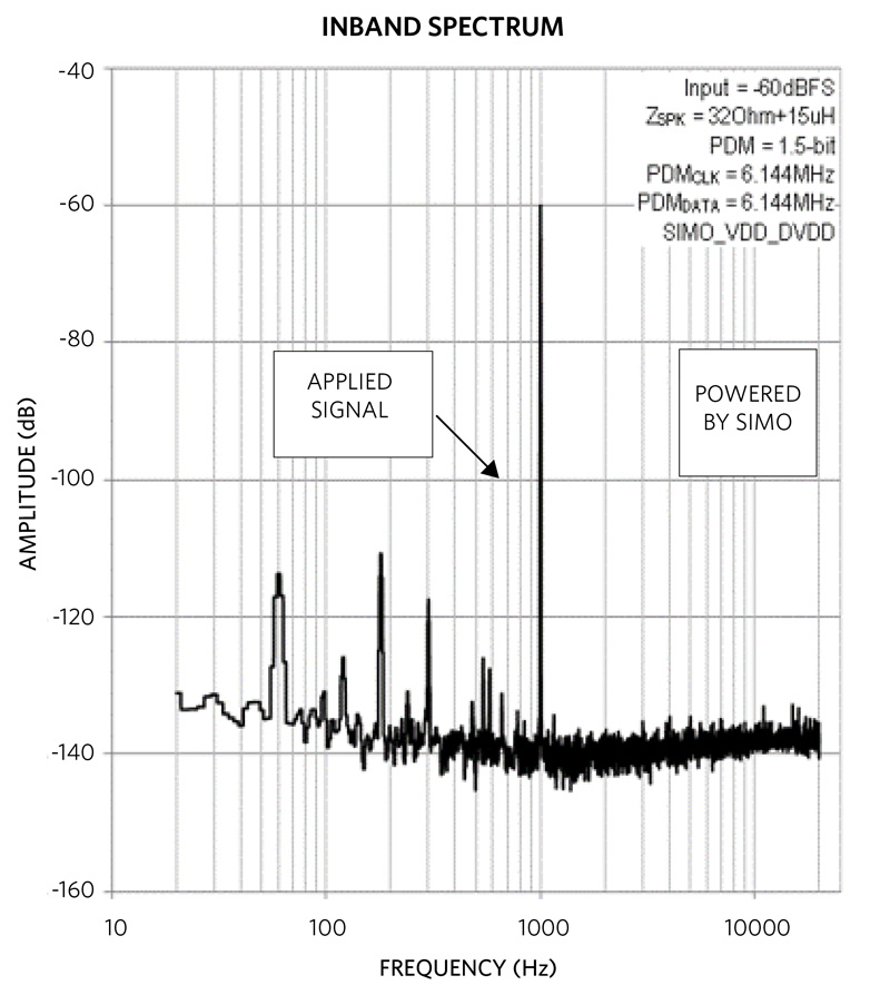
Figure 6(b) and 7(b) show the noise floor of the output signal when there is no input signal applied to the setups. When there is a -60dBFS input, the resultant spectrum of the output signal from the two setups are shown in the Figure 6(c) and 7(c).
The in-band spectrum FFTs show nearly identical noise and frequency content for LDOs supplying VDD and DVDD versus the SIMO supplying VDD and DVDD. The noise floor and the harmonic content are not affected by the SIMO driving VDD and DVDD supplies on the audio amplifier.
Click image to enlarge
(a). Audio Amplifier Test Setup with DVDD and VDD Powered by Discrete LDOs
Click image to enlarge
(b). Spectrum of the Output Signal When There is No Input Signal
Click image to enlarge
(c). Spectrum of the Output Signal When There is -60dBFS 1kHz Input Signal
Figure 6. Spectrum Tests with LDOs Powering the Setup

Click image to enlarge
(a). Audio Amplifier Test Setup with DVDD and VDD Powered by SIMO Outputs
Click image to enlarge
(b). Spectrum of the Output Signal When There is No Input Signal
Click image to enlarge
(c). Spectrum of the Output Signal When There is -60dBFS 1kHz Input Signal
Figure 7. Spectrum Tests with SIMO Powering the Setup
Conclusion
With the help of Maxim’s unique SIMO architecture, power can be efficiently delivered in a tiny package while achieving longer battery life for portable devices such as audio devices. Meanwhile, the programmable peak inductor current limit enables adjustable output voltage ripple for each SIMO output independently. This output ripple can be reduced to lower than 20mV. In addition, because of the nature of Maxim’s DCM SIMO, the spectrum of the output voltage signal is inherently spread out without a distinct carrier frequency that would have been highly prone to coupling and mixing.
All these features offered by SIMO regulators result in a perfect combination of high system performance and small form factor. The family of SIMO regulators featured in this article address the unique challenges in designing a successful wireless audio device – with ultra-low quiescent current, high efficiency, compact size, and good noise performance.
Maxim Integrated