Evolution of PV solar power architectures
PV modules, or panels, produce direct current (DC) electricity, typically with a peak output up to 250 Watts. With suitable control circuits, they can be used to charge a battery - which also generates DC, or to power DC devices. However, by far the largest market for PV solar installations is so-called "grid connect" applications. Here, the DC generated by solar modules is converted to alternating current (AC) for direct connection to the AC power grid. When solar power is not generated, for instance at night, the grid provides power for the user. When the solar installation is generating power, the user can power electrical appliances with it and any excess is sold back to the power company that supplies the grid.
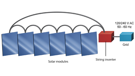
In conventional PV solar installations, modules are connected in series, like a daisy chain, to form a "string". A central inverter converts the high voltage DC output of the string to AC for connection to the grid. Figure 1 shows the arrangement.
Installation is complex and expensive for these conventional systems, requiring specialist skills and safety procedures due to the high DC voltages and currents that are developed. These can reach up to 900V at 5A - lethal if touched. In systems using DC strings, maximum energy harvesting occurs only when every module is matched exactly for technical performance and the same amount of solar radiation reaches each solar cell in every module. In real world conditions these requirements are often not met and the system performs below its potential, often dramatically so. Shading from any source such as tree branches or even something as small as an antenna or vent pipe can dramatically reduce the energy produced from string systems. Also, dust and dirt that build up unevenly on modules causes some modules or even a few cells of modules to see less solar energy than other modules. Because the modules are connected in series the whole system only performs at the level of the poorest performer in the string so a shadowed module limits the whole system and the higher potential energy of the other modules that are not shadowed is wasted. Under these real world conditions the penalty to the potential for energy harvest is severe. It is not uncommon for a system that has relatively few of its cells obstructed to perform at less than half its peak power capability and even not perform at all if such shadowing occurs on several modules in the system. Clearly, if the weakest modules have such a dramatic affect on PV solar system efficiency, it is important that modules are closely matched before installation. This adds to both manufacturing and installation costs. In addition, PV systems based on conventional architecture can only be installed on one plane on a roof, with the modules facing in one direction. If multiple planes are used, the whole system output is limited by the performance of the modules that receive the lowest level of light. Two further disadvantages of conventional PV installations lie in the central string inverter itself. First, it is a central point of failure. When it fails, all power from the solar installation is lost. Second, although very efficient, perhaps converting up to 99% of the available power from DC to AC, string inverters are large units that need to be located in protected environments indoors. Even then, most manufacturers of these inverters will only warrant the products for 5 or 10 years. In practice, a string inverter usually needs to be replaced at least once during the life of a PV solar installation. String inverters are big, expensive units. PV modules, on the other hand, typically perform well for 25 years.
Installing intelligent DC-DC converters behind each module, then feeding the DC voltage to the central inverter, overcomes some of the problems described above. Figure 2 illustrates the architecture.
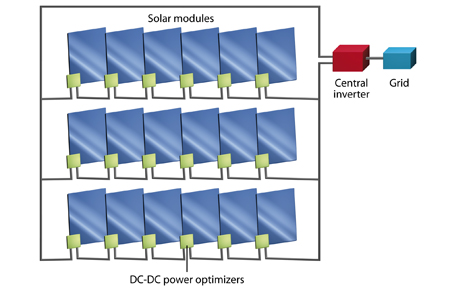
Using DC-DC optimizers maximizes the power harvested from each module by enabling per-module maximum power point tracking (MPPT). MPPT is an electronic technique that varies the electrical operating point of each module in order to extract the maximum available power from it. Using this architecture, any degradation in the performance of a module, due to clouds, shadows or other obstructions, does not affect the performance of other modules and has much less affect on the power harvested from the system as a whole. Installers don't need to match adjacent panels for best output and modules can be installed on any available roof space - they don't need to be on a single plane, as they do with a conventional DC string installation. In addition, the system can be monitored on a per-module basis, making it easier to identify the exact location of any problems that might occur over the life of the installation. Despite the benefits, the disadvantages of this architecture are significant. It adds around $200 to the cost of every module without eliminating the most expensive and weakest link in conventional PV solar strings - the central inverter. Furthermore, there is still high voltage DC to deal with, requiring specialist skills and equipment, with associated higher costs. What's more, the wiring and installation of these optimizers adds complexity and cost.
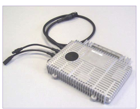
All of the advantages of DC-DC optimizers, but none of the disadvantages, can be realized by using micro-inverters. One micro-inverter is built into, or attached to, each PV module. This architecture is illustrated in Figure 3.

Each micro-inverter converts the DC from each module to AC, ready for direct connection to the grid. An example of a micro-inverter is shown in Figure 4.
The micro-inverter architecture allows each module to be an independent, standalone, solar AC grid connect system with its own optimized energy production output. Micro-inverters mean faster, simpler and safer plug-and-play installation. There are no high voltage DC circuits to handle and installation time and costs are cut by 15% to 25%. Further, the need for a large, hard-to-install, central inverter, which is the single most common point of failure in conventional systems, is completely eliminated. Installations are flexible and scalable, and modules can be located on any plane, or on multiple planes within a single system. Micro-inverters deliver between 5% and 15% more power from the installation and such systems are intrinsically safer. By eliminating the central string inverter - or several of them over the life of the system - the additional cost of adding a micro-inverter to each module is mitigated. In fact, it has been calculated that using reliable micro-inverters - those with a realistic operating life in excess of 25 years - enables the cost-per-harvested Watt of PV solar systems to be cut by up to 25%, compared with conventional systems. This dramatic improvement is in stark contrast to the small, incremental advances being made in the efficiency of PV modules over the last few years. Equally important from the installer perspective, micro-inverter PV systems allow monitoring down to the level of individual modules. Any faults that do arise are easily located, reducing maintenance costs. In fact, these monitoring systems can even be web enabled, so the status of the system can checked from anywhere in the world where there is Internet access. The monitoring systems also give users real-time and historical data on the performance of their system. Micro-inverters may not yet be as efficient as large central inverters, but because the overall yield from PV-systems based on micro-inverter architectures is so much higher, it is important not to be misled by headline efficiency figures. Efficiency is important but it's only part of the story. Micro-inverters represent one of the fastest growing parts of the solar-electric industry. The solar inverter market was valued around $2.4 billion in 2009 and is growing fast.
Micro-inverters are not a new idea. The challenge has been to design these products to be reliable in real-world conditions. Temperatures can easily reach +85 degrees C behind a solar module and high temperatures are not good for electronic devices. A rule of thumb used by electronics designers is that every 10 degrees C rise in temperature will halve the mean time between failures (MTBF) of an electronic system. The MTBF figure is a guide to the predicted failure rate during the so-called "useful life" period of a product. It's a statistical calculation based on the predicted failure rates of the individual components within the product. However, the concept of MTBF is widely misunderstood, and often misrepresented in marketing material. The inference made by some suppliers in the solar industry is that a high MTBF supports an expectation of a long life for their products. Such statements are wrong. An MTBF of 600 years sounds great but 100% of the products may still fail in an unacceptably short time. This is because wear-out mechanisms determine the lifetime of products, and these failure mechanisms are not predicted by MTBF. A product with an MTBF of 300 years could actually live 40 years before the wear-out mechanisms lead all of them to break down. By contrast, a product with 600 years MTBF might have wear out mechanisms that limit its life expectancy to 15 years or less. If you know this, you would clearly choose the 40-year life expectancy product over the 15-year life expectancy product. For a solar micro-inverter, this is very important. With a 15-year lifetime product you would have to replace all of them before the modules wear out, in about 25 years. With the 40-year lifetime product, you will only replace a few of them during the lifetime of the modules. Clearly, an over-emphasis on MTBF as a measure of real-world reliability is dangerous. A company may claim an MTBF of 800 years for its products but only warrant them for 10 years - the warranty is the better indicator of likely operating life. The safest approach is to select products that are backed by accelerated life test data derived from accepted test methodologies. For the solar industry, IEC 61215 is a recognized test methodology for solar modules and therefore an appropriate guideline for micro-inverters. Two further important indicators of reliability are the temperature range over which the micro-inverter is rated and the warranty offered by the micro-inverter manufacturer. Solar modules are typically rated from -40 to +85 degrees C. Why would you then choose a micro-inverter rated at a maximum temperature less than the maximum temperature for the solar module? Until now, the reliability of micro-inverters has been limited by the need to use relatively unreliable components in their manufacture. These problems are now being overcome. As a result, demand for micro-inverters currently outstrips supply (Q1, 2010).
For most rooftop PV solar installations in domestic and commercial premises, there is growing recognition that conventional DC string architectures are underperforming their potential for energy harvest. They are not delivering the efficiency required to enable more widespread adoption of solar-electric technology. The interim step of using DC-DC optimizers greatly improves energy harvesting, but at a cost that is unacceptable. The next few years will see micro-inverter based systems become widely adopted and a growing number of PV module manufacturers will build micro-inverters into their products. The AC module will become an industry standard module and installation time, complexity and cost will be dramatically reduced. At the same time, users will harvest more electricity from their systems and their investments will be paid back over much shorter periods. www.enecsys.com


