Harvesting and storage solutions
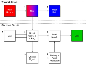
Advances in distributed sensors and sensor networks have led to an increased interest in renewable and autonomous power sources. The use of waste heat is an attractive source of energy for many applications where power on the order of μW-mW is required. The implementation of a thermoelectric power conversion and energy storage system requires several basic elements in addition to an assumed heat source and electrical load. These elements, shown in schematic form in Figure 1, are: 1) a thermoelectric power generator (TEG), 2) a heat sink, 3) a power conditioning circuit that provides voltage up-conversion and regulation, 4) an energy storage device such as capacitor or battery, and 5) a power (load) management circuit. The interaction of these elements is critical to the performance of the system. The following provides further detail about each key element of the system and issues that affect system optimization.
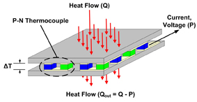
Thermoelectric Power Generator (TEG) The direct conversion of heat into electrical energy can be accomplished through the Seebeck effect in which heat flow through a thermoelectric device produces a voltage and current. The basic building block of any TEG is the PN couple. The PN couple consists of a single element of P-type and N-type thermoelectric material that are connected electrically in series. Heat carries the majority carriers from one junction to the other producing a current and voltage. By placing many PN couples in series electrically and in parallel thermally (see Fig. 2), a TEG can be constructed that generates a voltage proportional to the temperature differential (?T) across the elements. The current is a function of the number of PN couples. Heat Rejection In order to sustain a ?T across a TEG, there must be heat flow through the device. This requires a heat source and a heat sink capable of rejecting the heat passing through the TEG. Heat rejection can be accomplished in numerous ways including direct conduction to a large thermal mass, liquid cooling, spray cooling, phase change or simply through convection to the air using a traditional heat sink (the most common and often the lowest cost of these approaches). Heat sinks come in a vast array of sizes, dimensions and materials and choosing the proper one requires a thorough understanding of several key parameters. The parameter describing the ability of a heat sink to dissipate heat is the "thermal resistance," ?. A low thermal resistance means the sink will do a good job of rejecting heat to the environment while a high thermal resistance will do a poor job. The thermal resistance of any heat sink is affected by the following:
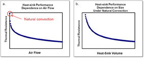
Airflow Speed - The speed of the air flowing across the fins or pins of a heat sink plays a key role in the ability of the sink to dissipate heat to the environment. Even a small amount of air flow across a sink can substantially improve its performance relative to a case with no forced airflow known as natural convection (Fig. 3a). A fan can be used to improve performance but the fan will impact the overall conversion efficiency of the TEG system. Size, Fin type, Dimension and Spacing - Size and geometry (such as aspect ratio), have a large impact on the performance of a heat sink (Fig. 3b). The optimal fin dimension and spacing depends on the fin material, mode of operation (natural or forced convection) and desired operating condition. Most applications seek to minimize the size of the heat sink. Such optimization requires understanding the operating boundary conditions like temperature and air flow to properly design the size, spacing and number of fins or pins. Thermal Spreading Resistance - A large mismatch in footprint area between the heat source, TEG and base of the heat sink can lead to additional thermal resistance often referred to as spreading resistance. Performance can be improved by using a more thermally conductive material (such as copper) and/or varying the base plate thickness of the heat sink. Gravitational Orientation - The performance of a heat sink in natural convection mode (i.e., no forced air movement) depends on the orientation of the fins relative to gravitational direction. The dependence of performance on orientation can be reduced somewhat by the use of pin fins rather than plate fins in the heat sink. Voltage Regulation and Power Management In cases where the ambient temperatures and heat flow are not constant, the output of the TEG will fluctuate. These fluctuations must either be tolerated by the load or eliminated by voltage conditioning and/or energy storage. Because the voltage output of a TEG is proportional to the temperature differential ?T across the TEG, if the ?T is small, it may be necessary to boost the voltage to the minimum usable value. Boost Converters (>400mV) - Many of today's electronics require a minimum of 1.8V to 3V to operate but the heat source and TEG combination may be unable to generate such a voltage. Fortunately, there are numerous commercially available boost converters that can convert voltage from as low as 400mV to greater than 3V. Micro-Power Up-Converters (>30mV) - Recent advancements in up-conversion now make it possible to up-convert voltages as low as 30 mV. This is particularly important in cases where the ?T available from the heat sources is very low. One example of this is generating power from the human body were reasonable and achievable ?Ts are in the range of only 5-10K. Energy Storage Energy storage is needed when continued operation of the load is required while thermal energy is unavailable. Two general types of storage are used that offer differing characteristics. (1) Batteries (cells) provide high energy storage density but since the energy is stored chemically, the discharge rate is slow. The term "power density" is used to describe the limits on energy discharge. The other type of storage device is the capacitor. (2) Capacitors store energy physically by charging plates that can be quickly discharged. While the energy storage density of capacitors is smaller than batteries/cells, they have high discharge rates or power density making them ideal for quick bursts of power. Systems will sometimes contain both types of storage especially if the load includes transient high-power devices such as a transmitter. Capacitors do not need any special circuitry to function well but batteries typically do. Charge management devices increase the lifetime of the battery or cell and are available from several manufacturers. They also aid in the performance of the system by allowing charging only when there is sufficient power available, in excess of what load requires. Power Management Lastly, power (load) management circuits switch the load between the boost convertor and the battery thereby isolating the cell from the output of the boost convertor. This benefits the cell by removing the drain and allowing it to charge when power is available directly from the boost convertor. This also minimizes the risk of a faulty or exhausted cell from shunting the output. www.nextreme.com


