Timing Challenges in Industrial Applications
Timing is critical to correct operation of industrial robotics and machine tool applications which involve the coordinated movement of several axes in space.
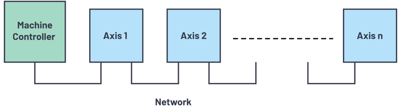
Figure 1. Network topology of a multiaxis machine
Robots typically have six axes that need to be controlled in a coordinated manner, and sometimes seven if the robot is moving along a rail. In CNC machining, 5-axis coordination is common, although there are applications that utilize up to 12 axes in which tools and workpieces are both being moved with respect to each other in space. Each axis comprises a servo drive, a motor, and sometimes a gearbox between the motor and the axis joint, or end effector. The system is then interconnected over an Industrial Ethernet network, usually in a line topology, as shown in Figure 1. A machine controller converts the required spatial trajectory to individual position references for each servo axis, and these are communicated over the network on a cyclic basis.
The Control Cycle
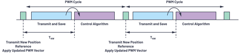
These applications run on a defined cycle time that is usually equal to, or a multiple of, the fundamental control/pulse-width modulation (PWM) switching cycle of the underlying servomotor drive. End-to-end network transmission latency is a key parameter in this context as illustrated in Figure 2. Within each cycle period, the new position reference and other relevant information must be transmitted from the machine controller to each node of Figure 1. Then there needs to be sufficient time remaining within the PWM cycle for each node to update the servo control algorithm calculation using the new position reference, as well as any new sensor data. Each node then applies the updated PWM vector in the servo drive at the same point in time via a distributed clock mechanism that is Industrial Ethernet protocol dependent. Depending on the control architecture, part of the control loop algorithm may be implemented in the PLC, and it requires sufficient time to be available, having received any relevant sensor information update across the network.
Click image to enlarge
Figure 2. PWM cycle and network transmission time
Data Transmission Delays
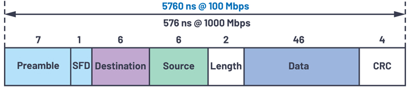
Assuming that the only traffic on the network is the cyclic data flowing between the machine controller and the servo nodes, the network latency (TNW) is determined by the number of network hops to the furthest node, the network data rate, and the delays encountered in each node. In the context of robotics and machine tools, the propagation delay of the signal along the wire can be neglected, as the cable length is typically relatively short. The dominant delay is the bandwidth delay; that is, the time needed to get the data onto the wire. For a minimum size Ethernet frame (typical for machine tools and robotics control), the bandwidth delay is illustrated in Figure 3 for both 100 Mbps and 1 Gbps bit rates. This is simply the packet size divided by the data rate. A typical data payload for a multiaxis system from controller to servo would consist of a 4-byte speed/position reference update and a 1-byte control word update for each servo, which means a 30-byte payload for a 6-axis robot. Of course, some applications will carry more information in the update and/or will have more axes, in which case packets larger than the minimum size may be needed.
Click image to enlarge
Figure 3. Bandwidth delay of a minimum length Ethernet frame
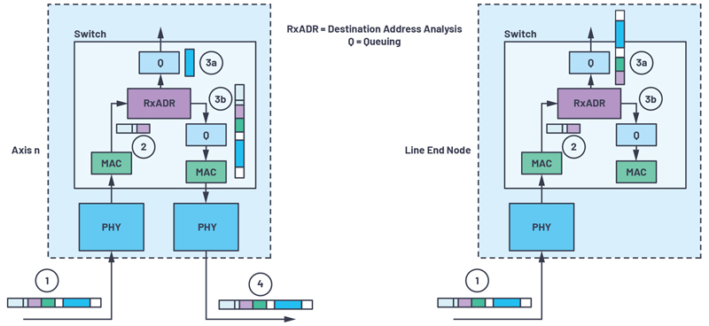
Apart from the bandwidth delay, the other delay elements occur as a result of the Ethernet frame passing through the PHYs and 2-port switch at each servo network interface. These delays are depicted in Figure 4 and Figure 5, where the movement of the frame is shown through the PHY into the MAC (1-2), through the destination address analysis where only the preamble and destination parts of the frame must be clocked through. Path 2-3a represents extraction of payload data for the current node, whereas path 2-3b represents the onward journey of the frame to the destination node(s). Figure 4a shows only the payload being passed to the application in 2-3a, whereas Figure 4b shows the bulk of the frame being passed; this is indicative of small differences that can occur between Ethernet protocols. Path 3b-4 represents the outbound transmission of the frame through the transmit queue, through the PHY and back out onto the wire. This path does not exist on a line end node as shown. Cut-through packet switching is assumed here, rather than store-and-forward, which has much higher latency as the entire frame is clocked into the switch before it is forwarded on.
Click image to enlarge
Figure 4. Frame latencies: (a) 2-port node frame latencies and (b) line end node
Click image to enlarge
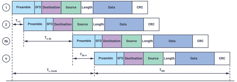
Figure 5. Frame transmission timeline
The delay elements of the frame are also shown in Figure 5 along a timeline, where the total frame transmission time through one axis node is illustrated. TBW represents the bandwidth delay, while TL_1node represents the latency of the frame through a single node. Apart from delays related to the physical transmission of the bits over the wire and the clocking in of address bits for destination address analysis, PHY and switch component latencies are the other elements that impact the transmission delays within the system. As the bit rates on the wire increase and the node count expands, these latencies become even more important in the overall end-to-end frame transmission delays.
Low Latency Solutions
Analog Devices has recently released two new Industrial Ethernet PHYs designed to operate reliably in harsh industrial conditions over extended ambient temperature ranges up to 105°C and with industry-leading power and latency specifications. The ADIN1300 and ADIN1200 were developed specifically to address the challenges outlined in this article and make ideal choices for industrial applications. With the fido5000 real-time Ethernet, multiprotocol, embedded 2-port switch, Analog Devices enables solutions for deterministic time-sensitive applications.
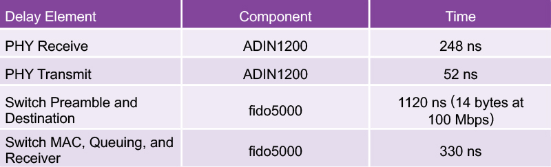
The latencies introduced by the PHY and switch are listed in Table 1, assuming that the receive buffer analysis is destination address based and assuming a 100 Mbps network.
Table 1. PHY and Switch Latencies
Click image to enlarge
As an example, aggregating these delays up to a 7-axis line network, and including the clocking of the full payload into the final node (3a in Figure 4), the total transmission delay becomes
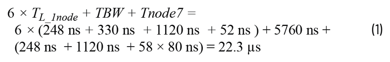
where the 58 × 80 ns represents the remaining 58-byte payload after the preamble and destination address bytes have been read.
This calculation assumes that there is no other traffic on the network or that the network is managed to enable priority access for time sensitive traffic. It is also somewhat protocol dependent, with slight variations in the calculation being introduced depending on the exact Industrial Ethernet protocol used. Referring back to Figure 2, in a machine system with cycle times down to 50 µs to 100 µs, the frame transmission to the furthest node can take up to almost 50% of the cycle, reducing the time available to update the motor control and motion control algorithm calculations for the next cycle. Minimizing this transmission time is important for performance optimization, as it allows longer and more complex control calculations. Given that delays associated with data on the wire are fixed and related to the bit rate, utilizing low latency components, such as the ADIN1200 PHY and the fido5000 embedded switch, is key to performance optimization, especially as node count increases (for example, 12-axis CNC machine) and cycle times reduce. Moving to gigabit Ethernet dramatically reduces the impact of bandwidth delay, but increases the proportion of overall latency introduced by the switch and PHY components. For example, a 12-axis CNC machine on a gigabit network will have a network transmission delay of approximately 7.5 µs. The bandwidth element of this is negligible, and it makes little difference whether minimum or maximum Ethernet frame sizes are used. The network delay is split approximately equally between the PHYs and the switches, underlining the value in minimizing the latency in these elements as industrial systems move toward gigabit speeds, control cycle times reduce (EtherCAT has demonstrated 12.5 µs cycle times), and node count expands with the addition of Ethernet connected sensors in the control network and the flattening of network topologies.