Author:
Matthew Russell, Master’s student at University College Cork, and a student engineer at Bourns Electronics Ireland
Date
03/29/2026
 PDF
PDF

Click image to enlarge
Figure 1: Gate driver circuit diagram with a Bourns transformer
While gate driver-based converters deliver improved efficiency, speed and signal integrity, their high frequency switching features can produce elevated levels of conducted electromagnetic interference (EMI), posing challenges to electromagnetic compatibility (EMC) and overall system reliability. To solve this issue, designers need to incorporate effective EMI management into these applications.
This article provides a comparative analysis of how transformer topology influences conducted EMI emissions in gate driver applications. Specifically, it compares a traditionally-used planar transformer with a concentric wound transformer. The measurement comparisons provided were performed using an internal evaluation board to ensure consistency and comparability across test conditions.
Gate Driver Background
High voltage power is seen as the cornerstone for clean energy delivery through electrification. It has shown to be particularly advantageous for e-mobility and renewable energy infrastructure. For these designs, wide band gap semiconductors enable efficient high frequency, high voltage operation due to their exceptional switching characteristics and low conductive losses. Silicon Carbide (SiC) modules typically require a positive gate voltage of +16V to turn on the device and a negative voltage of -4V to ensure reliable turn off. To supply these voltages, gate driver ICs commonly employ isolated power delivery through the use of push pull drivers, LLC converters or flyback converters. Isolation is achieved using transformers designed with sufficient insulation, creepage and clearance to meet application specific safety and regulatory standards.
Operating at elevated switching frequencies up to 1MHz (or even above) enables a more compact design and a higher power level but comes with an increased risk of unwanted electromagnetic emissions.
While the gate driver represents only one part of the overall power converter, it can be a significant source of common-mode emissions. One primary contributor is the conventional wire-wound isolation transformer. These transformers are known to introduce common-mode currents into the ground plane due to parasitic elements such as interwinding capacitance and leakage inductance.
An alternative is the planar PCB transformer, which offers several advantages:
A) Offers reduced interwinding capacitance that minimizes capacitive coupling. This helps to reduce common-mode noise due to the dielectric barrier between turns.
B) Provides a lower profile compared to traditional concentric wound transformers. The planar design has a reduced vertical height making it more suitable for compact or low-clearance applications.
C) Delivers improved manufacturing consistency. PCB-based windings enable high precision and low unit variations resulting in more consistent EMI performance.
Comparative Study Setup
The comparative study between a planar transformer and a traditional concentric-wound transformer performed by Bourns engineers focused on the impact on conducted EMI emissions in gate driver applications. To ensure consistency and reliability, all measurements were performed using a gate driver evaluation board. The board is powered by a clean 12V DC source from a battery to minimize external noise. Line Impedance Stabilization Networks (LISNs) were connected to both the positive and negative supply lines to provide a defined impedance and to enable precise EMI measurements.
The evaluation board’s key components included a buck regulator, isolated gate driver ICs (TI part number UCC25800), and linear regulators that generate isolated -4V/+16V rails for the switching gate drives. Figure 3 highlights these components in red on the board. The setup was designed as a controlled environment to evaluate the impact of transformer topology on conducted EMI emissions in gate driver applications. The test circuit has an operating switching frequency of 1MHz. At this frequency, increased interwinding capacitance in the transformer can significantly degrade EMI performance due to enhanced common-mode noise coupling.
Test Methodology
Devices Under Test (DUTs) compared two transformer topologies: a conventional concentric-wound transformer (DUT 1) and a planar transformer (DUT 2) using the LLC topology.
Each DUT is evaluated under identical operating conditions.
The conducted and radiated emissions were recorded across four EMI frequency bands:
Peak measurements were taken throughout. The results were plotted as dBμV versus frequency to visualize and compare performance.
Test Results
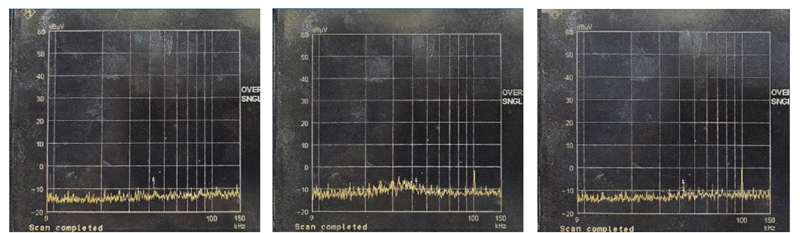
The conducted EMI measurements in the 9 kHz to 150 kHz low frequency band (Figure 2) showed very low emission levels, close to the noise floor for both transformers. These results indicate that transformer topology has a limited impact on EMI performance in this range, and that both DUTs operate well with applicable emission standards.
Click image to enlarge
Figure 2: At the 9kHz to 150 kHz frequency band, transformer topology has limited impact on EMI
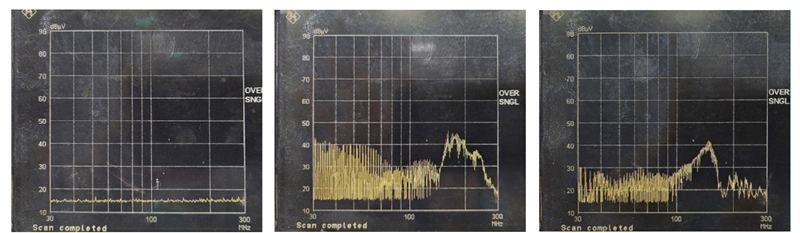
In the 150 kHz to 30 MHz frequency band (Figure 3), both transformers exhibited a prominent emission peak of approximately 50 dBµV at the fundamental switching frequency of 1 MHz. Additional peaks at harmonic frequencies further confirmed the presence of periodic switching noise inherent during high-frequency operation. DUT 2, which utilized the planar transformer architecture, demonstrated improved performance compared with DUT 1, which used a conventional concentric-wound transformer. The emissions in DUT 2 exhibited levels up to 10 - 15 dBµV lower at several higher frequency points, signifying improved suppression of conducted emissions in this range.

Click image to enlarge
Figure 3: Shows the measurements of both transformers in the 150 KHz to 30 MHz frequency band
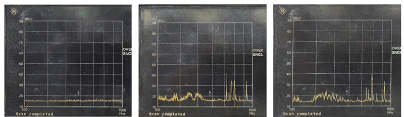
DUT 2 continued to exhibit lower overall emission levels across the 30MHz – 300MHz frequency band (Figure 4), further reinforcing its superior electromagnetic performance. These results validate the advantages of planar transformer in high-frequency LLC gate driver applications, particularly in terms of reducing common-mode conducted transformer emissions. Both transformers exhibited a noticeable increase in emissions between 150 MHz and 200 MHz, suggesting the presence of a common resonance or coupling mechanism within this frequency range.
Click image to enlarge
Figure 4: Illustrates the advantages of planar transformers in high-frequency gate driver applications
Similarly to the low frequency band, the high frequency 300MHz - 1000MHz range (Figure 5) exhibited broadly comparable performance across both transformers. This consistency indicates that transformer geometry and interwinding capacitance have a reduced impact on conducted emissions at higher frequencies, particularly beyond 600 MHz. These findings suggest that this transformer topology plays a critical role in EMI suppression at lower and mid-range frequencies.
Click image to enlarge
Figure 5: Shows the performance of both transformer types highlighting the need for EMI suppression
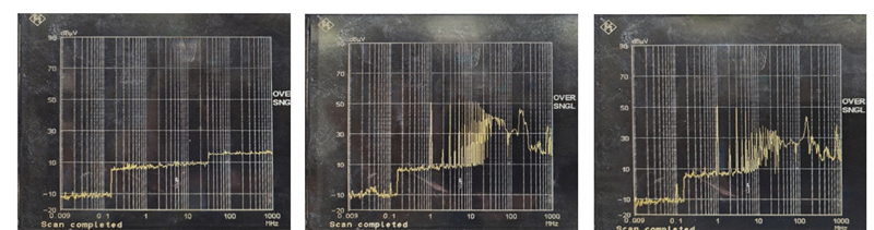
A single scan across the spectrum of interest from 9 kHz to 1000 MHz (Figure 6), DUT 2 delivers the lowest or comparable emission levels. Its performance is particularly notable in the critical 1 MHz to 100 MHz range, where switching harmonics and conducted noise are most prominent in gate driver applications. Within this band, the planar transformer outperforms the conventional concentric wound transformer by a significant margin. The planar transformer exhibits lower peaks, especially after the third harmonic. These results reveal that the planar design offers enhanced suppression of high-frequency noise, likely attributed to its optimized winding geometry, reduced parasitic capacitance, and improved shielding characteristics.
Click image to enlarge
Figure 6: Within the 9kHz to 1000MHz frequency band, the planar transformer exhibits superior EMI performance
Conclusion
This study demonstrates that transformer structure significantly influences the conducted EMI performance of gate driver circuits. While both transformer variants show comparable behavior in the low (9 kHz – 150 kHz) and high (300 MHz – 1000 MHz) frequency bands, marked differences emerge in the mid-frequency ranges between 150 kHZ and 300 MHz. The planar transformer (DUT 2) consistently exhibits lower EMI emissions than DUT 1 particularly between 1 MHz and 100 MHz, where switching noise and harmonics are most pronounced. Additionally, the lower profile of the planar transformer makes it especially suitable for space-constrained applications. The planar transformer was shown to be the more effective solution for conducted EMI compared with the equivalent wire wound version.