Author:
Dr.-Ing. Frank Schafmeister, Head of Power Electronics, Paderborn University
Date
12/24/2021
 PDF
PDF
Click image to enlarge
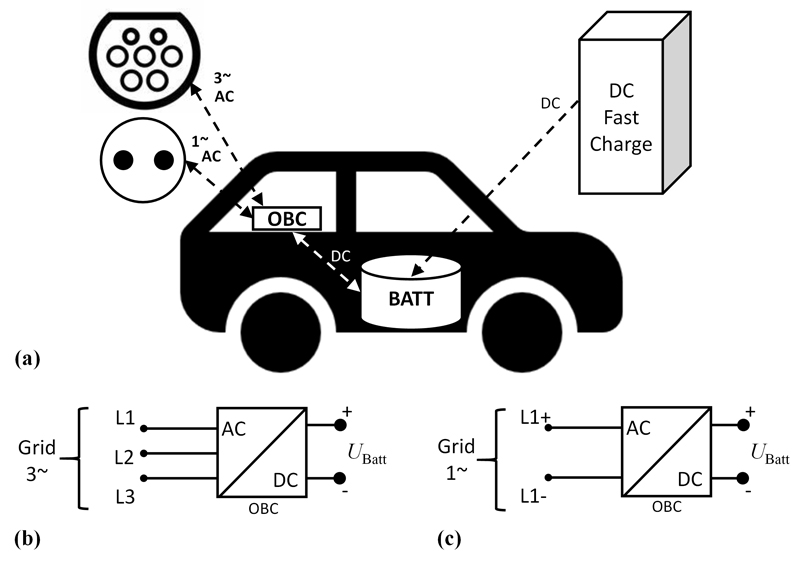
Figure 1: The traction battery of a xEV can be charged via a DC charging station or, via the OBC, from the AC grid (a). This article focuses on AC charging, especially on transformerless OBCs to be operated at (European) three-phase grids (b) and North-American single-phase (“split-phase”) grids (c)
On-board chargers (OBCs) charge the traction batteries of electric- and plug-in hybrid-electric vehicles (xEVs) from the AC grid. They work at raised power levels (11 kW, 22 kW) and should be able to handle various grid forms - however, the combination of operating from European three-phase grids and North-American single-phase (“split-phase”) grids causes difficulties when shifting to transformerless OBC architectures.
Those architectures with a simplified DC/DC converter as OBC output stage in principle promise a higher conversion efficiency as well as reduced weight and cost, in particular for future vehicle-to-grid (V2G) scenarios, where bidirectional power flow is required. Omitting the isolating transformer leads to various challenges (not only safety-related). By selecting an advantageous Power Factor Correction (PFC) rectifier circuit which forms the input stage of an OBC, high-frequency (HF) pulsating voltage potentials at the battery terminals can be avoided in spite of the missing transformer. Depending on the actual PFC topology and especially on the form of the supplying AC grid, low-frequency (LF) components (50-150 Hz) appear as common-mode voltage at the battery terminals and at the connected high-voltage (HV) system. Those common-mode voltages drive corresponding common-mode leakage currents through parasitic and explicit filter capacitances towards ground/chassis and to the connected protective earth (PE) conductor. These low-frequency leakage currents may provoke functional disturbances and must not exceed the legal limit of 3.5 – 10 mA. Research and development activities are ongoing to target dedicated compensation devices between the OBC input stage and the grid connector. They have to measure the low-frequency leakage current and then to actively compensate it. Instead, the method proposed in this article utilizes the OBC-internal DC/DC-stages to avoid the causative common-mode voltages and to prevent the resulting leakage currents. This is facilitated by a symmetrical DC/DC-double-stage, which is closed-loop controlled to keep the voltage potentials at the battery terminals constant. Switched-model simulations of the OBC verify that proposed approach. Moreover, the low-frequency voltage ripple at the DC-link capacitors at the critical operation on the North American split-phase grid is also decreased by about 35 %.
This article focusses on AC charging and discusses the challenges for the OBC if it handles various grid forms. Those architectures with a simplified DC/DC converter as OBC output stage (Figure 2) promise a higher efficiency as well as reduced weight and cost over conventional, transformer-based solutions. This applies in particular, but not only, for future vehicle-to-grid (V2G) scenarios, where bidirectional power flow through the OBC is required.
Click image to enlarge
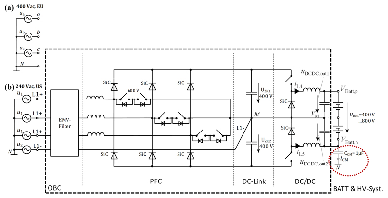
Figure 2: Exemplary topology of a transformerless OBC (unidirectional variant) for operation at European three-phase grid (a) and North-American split-phase grid (b)
Figure 2 shows an exemplary topology of a transformerless OBC (here as a unidirectional variant). The PFC-stage is based on a T-Type Vienna-Rectifier, but this variant connects the DC-link midpoint M to the grid-side in order to also allow single-phase operation. This topology variant shall be denoted as ViennaM. When charging from the three-phase grid M is connected to the Neutral-line N (Fig. 2a) and when using the US split-phase grid (Fig. 2b) M connects to the negative L1- line (120Vrms @ 180° phase shift referring to L1+ = ‘-120Vrms’, 60Hz). This way a similar voltage level between the three grid phase terminals (a, b, c or L1+, L1+, L1+) and the fourth grid return terminal (N or L1-) is kept, i.e. 230Vrms at the European three-phase grid and 240Vrms at the US split-phase grid. Considering a certain dimensioned current capability of the three phase legs in the ViennaM (e.g. 16 Arms each), the OBC power level for EU and US operation is also very similar (e.g. 11.0 kW for EU vs. 11.5 kW for US). However, tying the DC-link midpoint M to the grid return (N or L1-) and therefore to a defined potential provides another substantial advantage for transformerless OBC, as this measure prevents to a large extend high-frequency common-mode noise, which is a crucial fact when omitting the isolating and noise-suppressing transformer in the DC/DC-stage.
Click image to enlarge
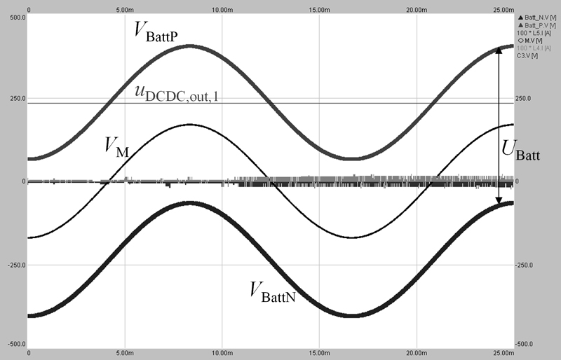
Figure 3: Simulated waveforms of the OBC at the split-phase grid (acc. to Figure 2) with conventionally operated DC/DC- stage for constant uDCDCout, 1/2 generating 60 Hz-varying battery potentials VBatt,p and Vbatt,n
On the contrary, if the proposed configuration of a symmetrical DC/DC-double-stage towards M is controlled in a way in order to keep the individual battery potentials VBatt,p and VBatt,n constant (Figure 4), no considerable 60 Hz common-mode current iCM = CCM dVBatt,n /dtwill result (Figure 5). The proposed approach compensates low-frequency common-mode voltage and -current upfront by the OBC-internal DC/DC-stage, obsoleting the need for dedicated compensation devices.
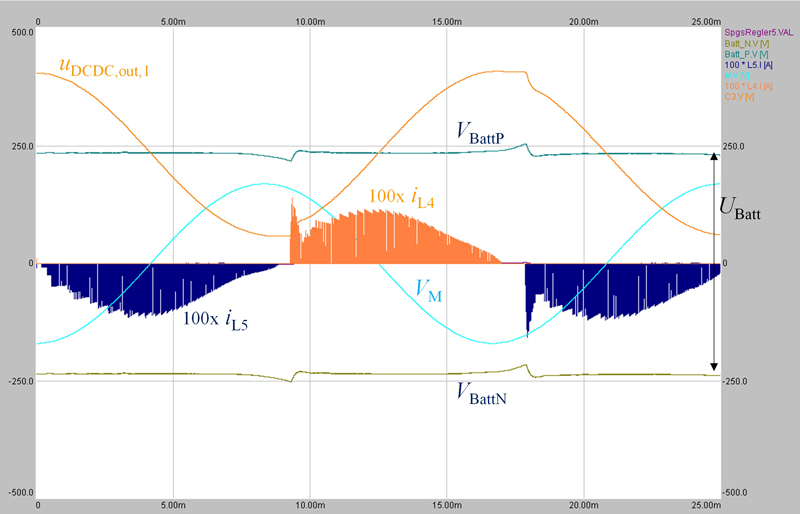
Figure 4 visualizes simulation results of the proposed common mode compensation method at US split-phase operation obtained from a switched OBC model with closed-loop current- and voltage control leading to constant battery potentials. Consequently, the DC/DC output voltages uDCDC,out,1and uDCDC,out,2(not plotted here) do show a 60 Hz-component compensating the oscillating midpoint potential VM. The extra current in the DC/DC-stage required for generating the 60 Hz-voltage component is limited to a peak value of îL4/L5,Bu ≈ 1A (for C3/4 = 1μF). The battery voltage UBatt = VBatt,p – VBatt,n is constant (here: 470 V).
Click image to enlarge
Figure 4: Simulated waveforms of the OBC at the split-phase grid (acc. to Figure 2) with the proposed symmetrical DC/DC-double-stage being closed-loop controlled for constant battery potentials VBatt,p and VBatt,n
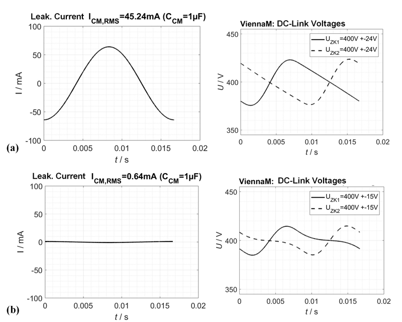
Figure 5 compares, based on the simulations, quantitative results for the transformerless OBC at US split-phase operation. Figure 5 displays the leakage current and the DC-link voltage ripple for a conventional DC/DC-stage with a conventional output voltage control. In contrast, Figure 5 showsthe leakage current and the DC-link voltage ripple for the proposed symmetrical DC/DC-double-stage, which is controlled for constant battery potentials in order to compensate the common-mode voltage. As a result, the leakage current is largely reduced and well below the limit of 3.5 mA. The DC-link voltage ripple (60 Hz) is also reduced by 37 %. In order to keep the same ripple, the DC-link capacitance could be reduced by roughly the same amount.
Click image to enlarge
Figure 5: Comparison of simulated waveforms of the transformerless OBC at US split-phase operation
(a) With conventional DC/DC-stage and/or it’s conventional output voltage control.
(b) With proposed symmetrical DC/DC-double-stage, when controlled for constant battery potentials
Conclusion
Switched-model simulations of the OBC verify the proposed approach: the leakage current is distinctively reduced. The low-frequency voltage ripple at the DC-link capacitors at the critical operation on the North American split-phase grid is also decreased by about 35 %, promising the DC-link capacitance to be reduced by the same amount.