Transforming EV Charging with New Winding Techniques
New winding techniques help to minimise losses in transformers for EV charger and renewable energy applications
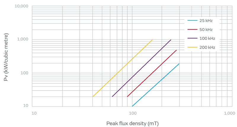
Figure 1: Core losses for a typical ferrite material – source Ferroxcube 3C90 data
Modern power conversion techniques all push towards higher efficiency for good reason; energy saving is clearly important but there are applications where functionality is also enhanced. Examples would be alternative energy systems such as solar and wind, and electric vehicle chargers where fewer losses equate to shorter recharging times or longer range for a given charge time. Better efficiency can also yield smaller, lighter and cooler-operating equipment, enhancing usability and reliability. An enabling technology for higher efficiency has been the introduction of wide band-gap semiconductors such as silicon carbide (SiC) and now gallium nitride (GaN), which have reduced switch losses dramatically with their low on-resistance, fast switching and low device capacitances.
With such improvements in semiconductors, focus has increasingly shifted to losses elsewhere in power converters, particularly in magnetics. Previously, losses in high-frequency transformers, for example, were not considered substantial for system efficiency considerations. Now, however, just 1% of output power dissipated in a transformer could be the whole loss budget. Over the years, better materials have lowered core losses, but winding techniques are often still rooted in the 19th century. Now that operating frequencies have increased, the form of the windings themselves is a significant factor in losses. There have been advances, though, with recent innovations in winding technique.
Transformer loss elements, core-related
Hysteresis loss derives from the energy required to alternately align core magnetic domains as magnetisation continuously reverses with applied high-frequency current. The loss can intuitively be seen as related to frequency, or the number of times per second the domains are reversed and the degree of magnetisation of the material or flux density (teslas). This in turn is proportional to voltage applied to a driven winding at frequency and inversely proportional to core cross-sectional area and number of turns on the winding. The constants of proportionality vary with temperature and frequency for different mixes of core materials, so the best guide to actual losses is the published curves by core material manufacturers, Figure 1 for example, adapted from Ferroxcube 3C90 material data.
Losses can be predicted in theory from the Steinmetz equation and its derivatives, but the original work was for sinusoidal waveforms only and the refinements for more general waveforms are largely empirical, relying on manufacturers to supply coefficients for the equation derived from their practical tests. The published graphs are therefore a better source of loss data, although these will not necessarily match actual operating conditions, which might have a varying DC offset magnetisation for example.
Eddy current losses occur in the bulk of the core material, induced by the magnetic field set-up by windings. Losses, again increasing with frequency, depend on the resistivity of the material, but modern ferrites, particularly nickel-zinc, have high values - around 105 Ω cm at 100 kHz, dropping to 104 Ω cm at 10 MHz, which produces insignificant loss at typical power switching frequencies.
There is a residual core loss related to mobility of magnetic domain walls, which cannot be accounted for directly by eddy currents or hysteresis, but the typical value has been found to be negligible.
Transformer loss elements, winding-related
Winding losses ultimately occur due to current through the resistance of the metallic winding. However, the current can have different DC and AC components, which cause the current to flow only on the surface of conductors (skin effect) or to flow in other conductors (proximity effect). Both effects are caused by eddy currents produced by changing magnetic fields around windings, similar to eddy currents in the core, but considerably higher in amplitude due to the intentional low resistivity of the winding material.
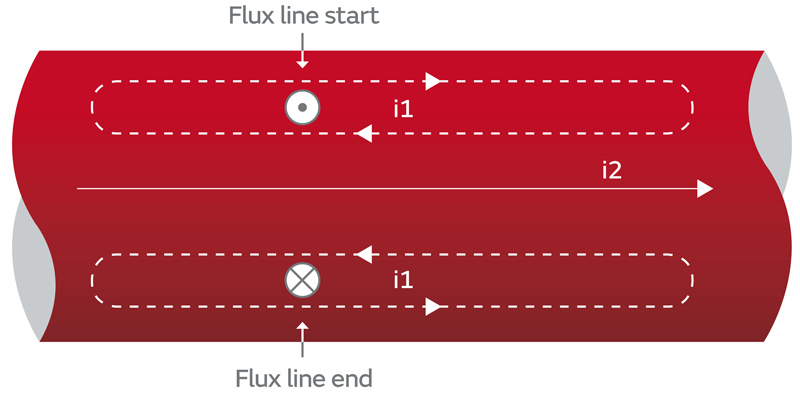
Skin effect is caused by eddy current 'loops' resulting from changing magnetic field lines inside a conductor induced by current through the same conductor. The loops are not discrete, just as the field is not really 'lines', but the effect can be represented by one long loop or many small ones, with the radial currents cancelling each other out. Figure 2 shows how the current loops are additive to the overall current at the edges and tend to be subtractive at the centre. The effect depends on frequency and the temperature-dependent resistivity of the wire, typically copper or aluminium. The degree of current cancellation in the wire centre, or equivalently current penetration depth δ, for copper at 80°C, is given by:
For minimum skin effect, the conductor diameter should be less than twice the penetration depth, for example less than about 0.45 mm at 100 kHz.
Click image to enlarge
Figure 2: Induced current i1 in loops cancels overall current i2 in the conductor centre and reinforces at the surface, causing skin effect
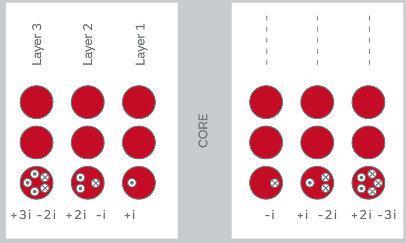
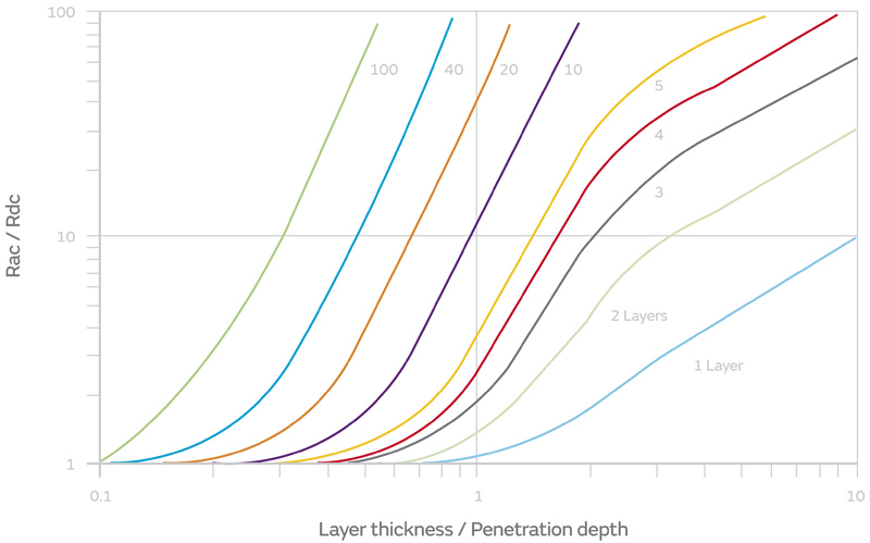
Proximity effect is similar to skin effect, except that the effects of a winding's magnetic field on other windings is considered. Again, the changing field from one conductor causes current 'loops' in adjacent conductors or windings with addition and cancellation effects, as in the skin effect. A common example is primary and secondary transformer windings, where the effect causes current 'crowding' on the adjacent winding surfaces with an increase in power dissipation due to the reduced effective cross-sectional area. Proximity effect also occurs between turns of the same winding when layered, with the current crowding increasing cumulatively (Figure 3). In each wire the total current, i, is the same but in the second layer it is made up from +2i and -i in the outer and inner wire surfaces respectively, and in the third layer +3i and -2i and so on. The increased localised current then causes exponentially increasing losses with layer count. For this reason, proximity effect losses are minimised with fewer layers in long narrow winding windows, although this is not often a practical arrangement. P.J. Dowell computed the effect of multiple layers on the increase in AC resistance over DC resistance Rac/Rdc for different ratios of winding thicknesses to penetration depth (Figure 4). As an example, with winding thickness equal to penetration depth (1 on the X axis), a ten-layer winding would have an AC resistance ten times higher than its DC resistance.
Click image to enlarge
Figure 3: Current crowds increasingly in winding layers, although net current is the same. Here dots and crosses represent current out and in, respectively
Click image to enlarge
Figure 4: Dowell's curves for AC resistance increase with layers and penetration depth
Winding self-capacitance has an indirect effect on losses; a fast switch such as SiC driving a transformer primary has to charge and discharge external stray capacitance which circulates current around the switch, causing losses. Leakage inductance can also cause external dissipation and voltage transients and is caused by energy stored in the gaps between windings.
Interleaving mitigates losses
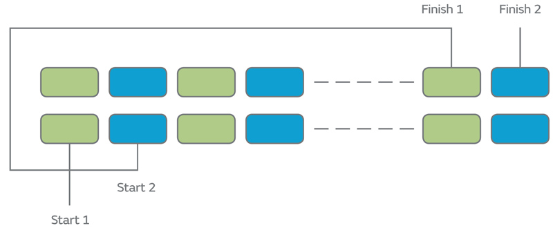
The various loss effects can be mitigated by using thin 'strip' conductors and interleaving of the primary and secondary windings. If wide strip windings are used for primary and secondary, face to face, they can have a large cross-sectional area for current handling but minimal skin effect, if thin enough. At the same time, if layers of primary are interleaved between layers of secondary, the high magnetic field intensity seen between simple windings is now divided between the interleaved primary-secondary interfaces, reducing the level of induced eddy currents and consequent losses. The reduction in field intensity between windings also reduces energy stored in the gaps, which translates to a reduction in leakage inductance - just sandwiching the secondary between a split primary, the simplest form of interleaving, reduces leakage inductance by a factor of four, as inductance scales with the square of field intensity. Generating many physical primary-secondary interfaces does however pose a challenge for isolation rating. Multiple primary or secondary layers still produce proximity effect losses within individual windings, but interleaving helps again here - the number of effective layers can be reduced by the winding technique shown in Figure 5. For example, instead of a simple two-layer twenty-turn winding, two strands or strips are wound bi-filar ten times with the end of one winding connected to the start of the other external to the transformer. The effect is to maintain a constant inter-winding voltage, reducing capacitive current and energy stored.
Click image to enlarge
Figure 5: Interleaving within winding layers reduces losses
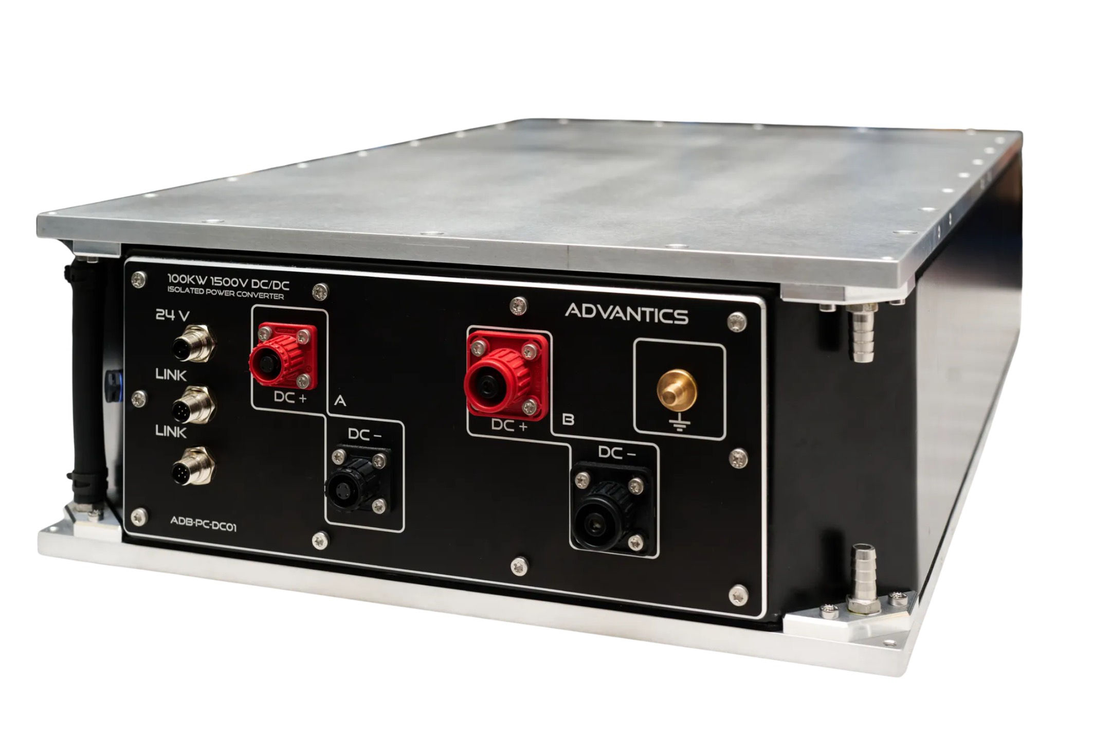
Winding construction breakthrough
A patent-pending innovation in winding arrangement by Murata has made interleaving of strip windings with high isolation a practical solution. Custom products (Figure 6) using the pdqb winding technology, rated from 30 kW to over 250kW and operating at frequencies up to 250kHz, feature efficiencies of better than 99.5% with leakage inductance typically less than 0.1% of winding inductance. The parts are targeted at applications such as EV fast chargers with input and output voltage variants from 50 V to 1000 V possible, with turns ratios of 1:1 to 10:1 at agency-approved isolation ratings up to 10 kV. The techniques utilised to reduce losses yield products that break the power/frequency barrier that limits practical transformers constructed using conventional litz wire or foil. One 100 kW application showed 80% reduction in winding losses and a 25°C drop in hot-spot temperature compared with a litz-wound solution, all in a reduced product volume. The pdqb windings also allow very efficient heat transfer to the product casing which, with its flat faces, allows for the simple implementation of a variety of cooling techniques.

Click image to enlarge
Figure 6: Murata's high power, high frequency transformer with innovative 'pdqb' winding technology
High power conversion applications such as in EVs and alternative energy need no longer be constrained by lossy conventional transformers. The innovative pdqb series from Murata opens up a world of opportunities for energy, cost and size savings, with consequent user benefits.