The Zth of a power module is used to calculate device lifetime
Fig. 1. Comparison of measurement with FEM-Simulation and calculation results
Transient thermal resistance (Zth) of power modules determined by simulation and measurement.
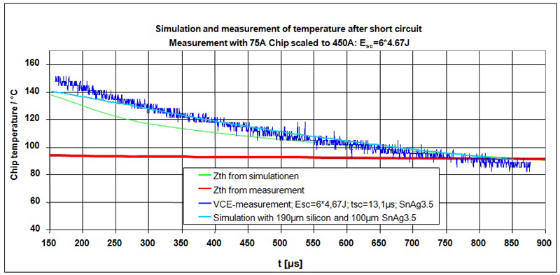
The transient thermal resistance (Zth) of a power module describes a key performance that is used to estimate the maximum output current for transient loads. It can also be used to calculate the temperature ripple as with a mission profile and resultant the lifetime of the power module. When dimensioning a power electronics system, the transient thermal resistance (Zth) of a power module is required to calculate the lifetime. The Zth has a significant influence if different power modules are investigated in the same application, as the heat capacity reduces the temperature ripple for a limited time. Precision and accuracy is required to calculate the correct temperature ripple. Simulation and VCE(T)-measurement based Zth are used to calculate the temperature in an IGBT module after short pulses with high peak losses. The temperature gradient shows significant differences, and only simulation-based Zth agrees well with the test results from short pulses. Delays between switch-off of load current and the start of measurements in large power modules have a significant impact on the short-time thermal resistance. Depending of inverter output frequency, the deviation in short-time thermal resistance influences the calculated temperature ripple, and therefore the predicted lifetime. Making use of Finite Elements simulation to determine the transient thermal resistance Zth ensures the correct calculation of short-time thermal behavior for the lifetime prediction. Determination of transient thermal resistance Zth According to e.g. JEDEC standard (JESD24-12), in the measurement of an IGBT, the temperature-dependent forward voltage drop for a small sense current is measured after heating the device with a load current. To measure the transient temperature behaviour, the cool-down phase is checked to determine a virtual junction temperature, which represents the average temperature distribution in the chip. As a second method, FEM-Simulation can be used to calculate the Zth. 3D CAD-Data and material properties are used to simulate the transient temperature distribution and extract the average temperature in the chip. Differences between measured and simulated Zth A simulation of the short puls test with Zth Foster models derived with simulation and measurement methods is performed. The calculation results are compared with extrapolated measurement results of the temperature after a short pulse with high peak losses with a single chip. Only the Zth Foster model derived from simulation shows good agreement with the measurement. Better results can be only achieved with direct FEM-Simulation as shown in Figure 1.
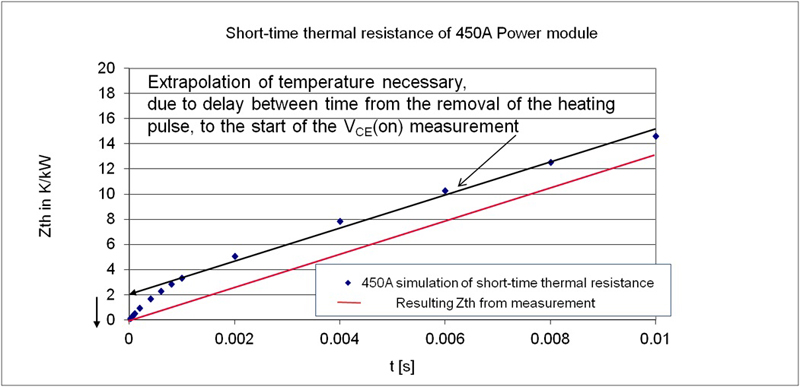
Simulating the Zth measurement process gives an explanation for the deviations. As shown in Figure 2, during the measurement process a linear extrapolation for the short time is per-formed.
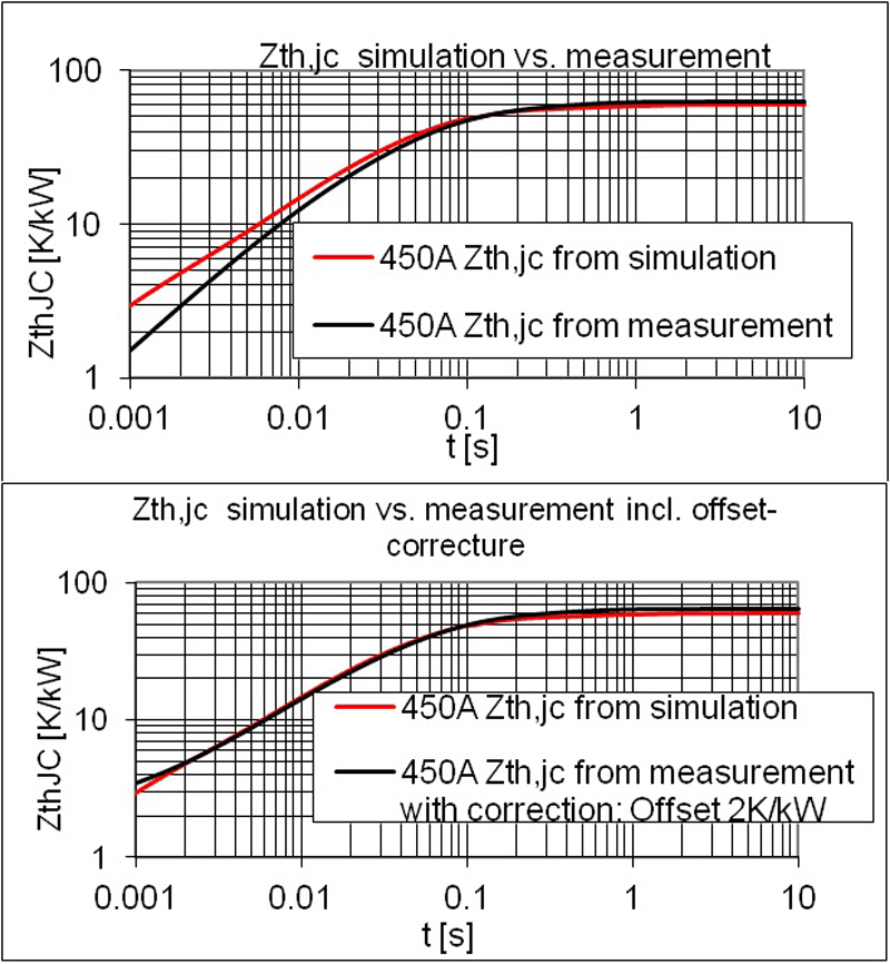
The simulation result shows a strong change of temperature gradient (up to 1ms), resulting from varying thermal properties in the stack consisting of silicon solder and copper in the top part of the stack. The resulting negative offset reduces the Zth,jc in the short-time. To check whether further factors cause deviations between simulation and measurement based Zth,jc curves, the influence of the offset is investigated. In Figure 3 the Zth,jc derived from measurement data is corrected with the offset calculated in Figure 2. Correcting the offset this results in good alignment with Zth,jc from simulation. Consequently no further effects are creating deviations between measurement and simulation of the transient thermal behavior.
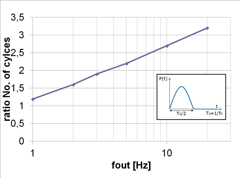
Influence on the temperature ripple and life time The influence of deviation between Zth from simulation and measurement on the temperature ripple during inverter operation is investigated in two cases. In the first case a typical three phase inverter configuration under the assumption of sinusoidal output currents at inductive loads is considered. The junction temperature therefore oscillates with the output frequency. Although for selected operation conditions the average losses might be the same, the ripple and therefore the peak junction temperature increases at lower frequency and decreases with higher frequency. Based on the power cycling curves for IGBT4, a possible number of cycles for the different temperature ripples was calculated, where ?T less than 10K for frequencies greater than 20Hz were neglected. Calculation results as a ratio of possible cycles calculated based on Zth from simulation to possible cycles calculated based on Zth from measurement are shown in Figure 4. The lifetime calculation based on Zth from measurements for frequencies greater than 1Hz seems to be more optimistic. This corresponds, however, to the part of the Zth, which in measurements is inaccurate.
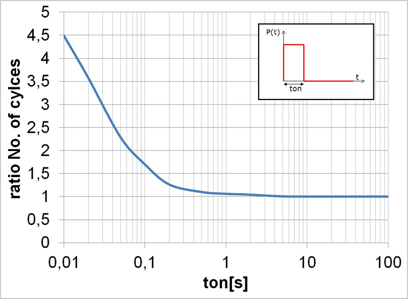
Because for frequencies greater than 20Hz the temperature ripple is negligibly small, in the second case, a rectangle load current shape to represent the varying load profile was used. When changing the duration of the pulse (ton) resulting temperature ripples and possible numbers of power cycles were calculated based on Zth from simulation and measurement. A ratio of possible number of cycles is shown in Figure 5. In both cases, the lifetime calculation based on Zth from measurements for ton times of less than 1 second (or frequencies greater than 1Hz) looks more optimistic. Determining lifetime on the basis of Zth from extrapolated measurements will predict too optimistic results if the mission profile contains a lot of short power pulses with significant amplitude. However, for many common applications relevant load pulses are generally longer than 1 second, which does not affect the calculation error of lifetime. A precise transient thermal resistance (Zth) is required to calculate the temperature ripple as a result of a mission profile, especially for low inverter output frequency. The delay time between removing the heating and starting the VCE measurement and additional noises on the measurement signal requires an extrapolation. This results in a negative offset, when measuring the Zth with the VCE method and applying a linear extrapolation. Making use of Finite Element simulation to determine the transient thermal resistance Zth ensures a correct calculation of short-time thermal behavior for the lifetime prediction. Infineon Technologies