Author:
Chengyuan He, Staff Application Engineer at Alpha and Omega Semiconductor
Date
11/09/2021
 PDF
PDF
Click image to enlarge
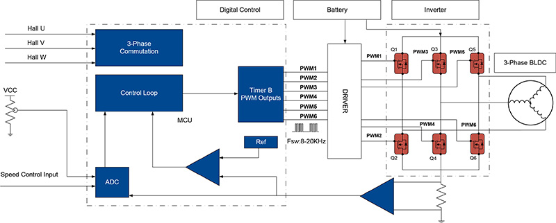
Figure 1: Key Functional Blocks of BLDC Power Tool
Introduction
Brushless DC Motors (BLDC) have been increasingly used in industry, due to demand for improved functionality, precision, and better utilization of primary energy sources. BLDC features include large torque-to-volume ratio, high reliability, small size, and low cost. There are two major commutation techniques: Trapezoidal and Sinusoidal Commutation. Back EMF waveforms and rotor-position sensing for the two techniques are different. Motor back EMF waveforms clearly identify which commutation technique is used. Trapezoidal commutation methods implement a low-resolution shaft-position sensor, to synchronize the switching of the drive transistors with the rotor position. Substantial field weakening is not required for trapezoidal commutation. For sinusoidal commutation, back EMF is sinusoidal, and an encoder (or resolver) is used to obtain rotor position. In this article, a six-step BLDC motor with a closed-speed loop applied to the power tool, has been built using discrete components. Figure 1 shows the key functional blocks: digital control, battery, driver, inverter, and 3-phase BLDC. The commutation will be introduced in detail to synchronize the six-step BLDC control. The power loss breakdown for power tool BLDC control is analyzed based on AOS AON6500 MOSFET Evaluation Board. This EVB provides good guidance of trapezoidal commutation distribution of MOSFET power losses for power tool application.
Block (Trapezoidal) Commutation
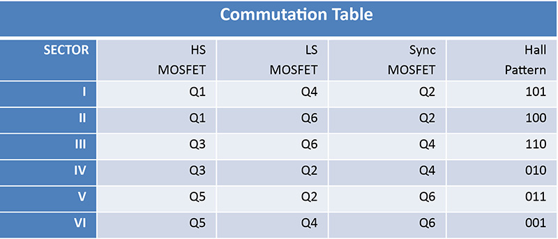
There are six sectors of operation in a block-commutation scheme. These are shown in Table 1 including two kinds of commutation: two-phase high-side commutation and two-phase low- side commutation.
Click image to enlarge
Table 1: Six Sectors of Operation in a Block-Commutation Scheme
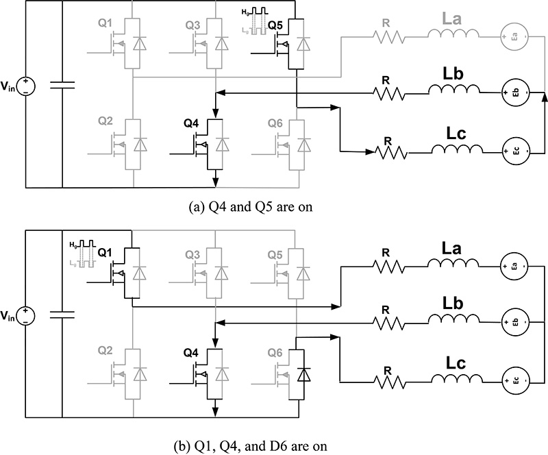
Figure 2 shows the commutation from Phase CB to Phase AB. During the commutation from phase CB to phase AB, Q5 remains off, after being on for 120 degrees. After Q5 is off, current flows back through the body diode (during the dead time) and Q6 until the energy stored in the Phase C winding disappears. Since the cathode of the Q6 body diode is connected to GND, its anode voltage decreases to the GND voltage, while the freewheel current continues flowing. Next, the voltage at the Phase C terminal equals the back-EMF voltage. Phase A (Q1 and Q2) will keep complementary switching, and Q4 is always on during the following step sector.
Click image to enlarge
Figure 2: Commutation from Phase CB to Phase AB
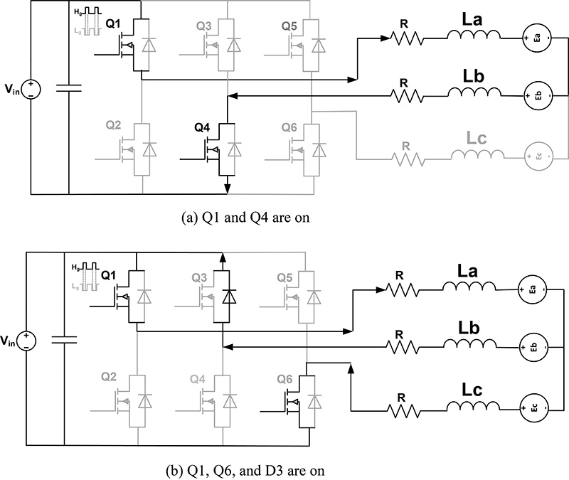
Figure 3 shows the commutation from phase AB to Phase AC. During the commutation from phase AB to phase AC, Q4 remains off after being on for 120 degrees. After Q4 is switched off, current flows back through the Q3 body diode until the energy stored in the Phase B winding disappears. Since the cathode of the Q3 body diode is connected to Vin, its anode voltage decreases to the Vin voltage while the freewheel current continues flowing. Next, the voltage at the Phase B terminal becomes equal to the back-EMF voltage. Phase A Q1 and Q2 will keep complementary switching, and Q6 is always on during the following step sector.
Click image to enlarge
Figure 3: Commutation from phase AB to Phase ACPower Loss Distribution
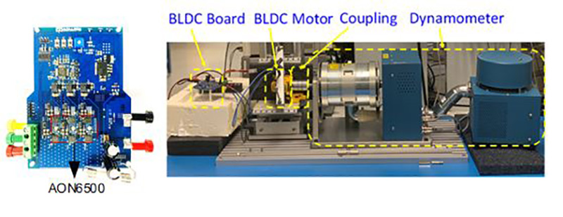
The BLDC system control board and testing setup are shown in Figure 4. Figure 5 shows the MOSFET AON6500 switching waveform. MOSFET switching frequency is 20 kHz. The motor has two pairs of poles, which means the electrical speed is twice the mechanical speed. The following power loss dissipation is based on the motor speed of 5110 rpm, and 0.32 duty-cycle ratio.
Click image to enlarge
Figure 4: BLDC System Control Board and Testing Setup

Click image to enlarge
Figure 5: MOSFET AON6500 Switching WaveformSee Figure 5
Figure 6 shows the MOSFET AON6500 power dissipation used for power tool BLDC. The turn-off loss is 56.31% of total power loss, which is the first maximum power dissipation. The turn-on power loss is 27.56% of total power loss, which is the second maximum power dissipation. The third biggest dissipation is conduction loss, at 12.94%. The low-side turn-on and turn-off losses can be neglected because the MOSFET switches at nearly zero voltage. For complementary switching control in one phase, the high-side MOSFET and low-side MOSFET keep complementary switching. In another phase, the low-side MOSFET is turned on; and in the remaining phase, both the high-side and low-side MOSFETs are turned off. From the above description, the low-side MOSFET conduction loss should take the maximum power dissipation. As shown in Figure 4, the low-side MOSFET takes 84.8% of the total low-side MOSFET power dissipation.
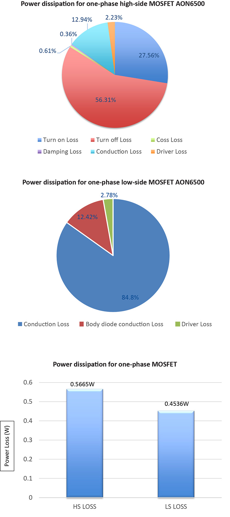
Click image to enlarge
Figure 6: MOSFET AON6500 Power Dissipation used for Power Tool BLDC
Conclusion
This article describes the power losses for trapezoidal commutation brushless DC Motor based on AOS MOSFET AON6500, as applied to power tools. Power distribution was analyzed using AOS BLDC Evaluation Board. The turn-off loss takes the maximum percentage of total high-side MOSFET power loss. For the low-side MOSFET power loss, the conduction loss is the biggest one. It gives good guidance of trapezoidal commutation brushless DC motors control board design and MOSFET selection.
Alpha and Omega Semiconductor, Inc.
Reference
1) App note: MOS-011,“Trapezoidal Commutation for Brushless DC Motor,” Alpha and Omega Semiconductor, Inc.
2) He, C.; Wu, T. Permanent magnet brushless DC motor and mechanical structure design for the electric impact wrench system. Energies 2018, 11, 1360.