Innovative magnetic materials together with advanced simulation and design technologies are bringing greater power capability in smaller packages.
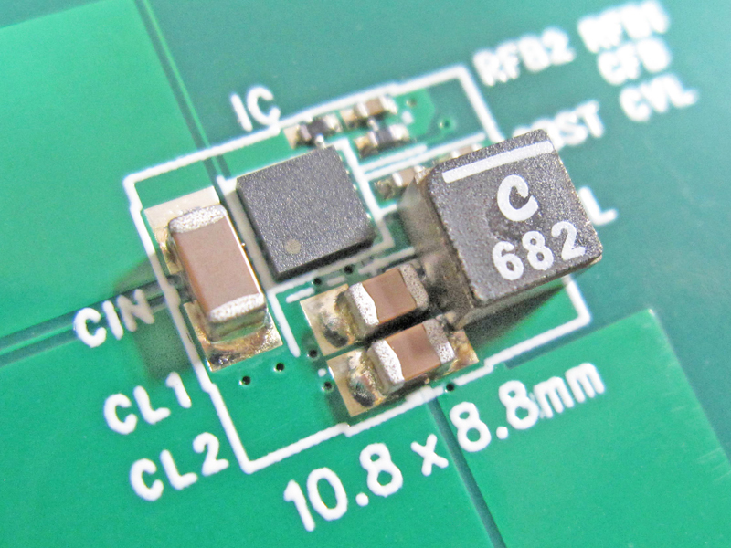
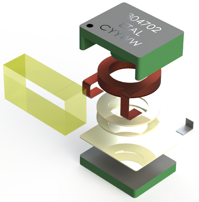
Figure 1 - Complete 3D CAD tool suites offer capability to create production level drawings
For many designers these magnetic and electromagnetic components are considered very “low tech”. The reality is, however, that much technology and know-how is applied to designing and constructing these passive components: moving their capability inexorably forward.
Technological developments - energy efficiency, weight minimisation, surface mounting and miniaturisation - have been major factors in driving advancements in this sector. Future growth in the markets for electronic coils, transformers and other inductors will be driven by improved, high-tech electronic components.
Developments in materials, construction techniques, equipment and design solutions are creating new optimised solutions across a range of applications.
It all starts with DESIGN. Practical electromagnetic component design requires knowledge of electrical principles, materials, as well as cost constraints. While simple devices, for example low-voltage transformers under 10 kVA, may be designed using handbook data and pencil-and-paper calculations, whereas specialist devices and more complex or larger items require many iterations and verification with computer aided modelling (CAM).
Basic physics drives advanced simulation and design
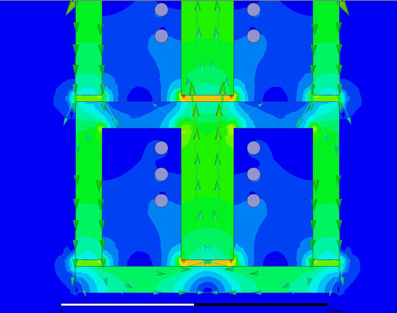
Even the most sophisticated design and analysis have at their heart the fundamentals of magnetic and electrical circuits - Maxwell's equations, Ampere’s law, Faraday’s law, Gauss’s law and Lenz’s law. Best in class design software takes these fundamentals and apply todays’ electromagnetic field simulation and modelling with sophisticated computation and visualisation techniques. For example, ETAL harnesses the power of simulation software based on the finite element method to simulate a wide range of electromagnetic fields when designing components. Examples run from 2-D magnetic transient, AC electromagnetic, magnetostatic, electrostatic and DC conduction to electric transient solvers. This will accurately solve field parameters including capacitance, inductance, resistance and impedance.
Results from this analysis enable a full 3D CAD drawing to be produced. Customers can then move forward with the mechanical and electrical design of their system without the need for physical samples of the finished component.
Very accurate models of magnetic components created within the CAD package provide the means to try-out the impact of different materials, wires and air gaps, tuning the design to get as close as possible to the parameters required by the customer. Using simulation to tune the design allows optimum performance to be achieved without the need to create multiple prototypes.
With design and analysis based on solid engineering principles and state-of-the-art simulation techniques, designs can push the envelope by integrating new magnetic materials, wires, winding and manufacturing techniques at the earliest possible stage.
Magnetic materials innovation
For the electromagnets used in inductors, transformers, DC-DC converters and the like, designers look for core materials that deliver high permeability and maximum flux density. Iron and alloys like SiFe are the traditional starting point.
Click image to enlarge
Figure 2 - Electromagnetic field simulation
Ferrites - ceramic, homogeneous materials are composed of various oxides. Those with iron oxide as their main constituent exhibit excellent EMI protection against common mode and differential conducted noise, since their insertion loss is proportional to frequency - thereby showing no attenuation to signals, but high impedance to high frequency noise.
Working temperature, flux density and frequency are the key parameters to select the optimal material for power conversion applications. Specific materials enable components to operate from just a few kHz through to hundreds of kHz and even MHz, providing high efficiency, compact converters.
Powder cores are distributed air gap cores that are primarily used in power inductor applications, specifically in switched-mode power supply (SMPS) output filters, also known as DC inductors. Other power applications include differential inductors, boost inductors, buck inductors, and flyback transformers.
Different core materials have particular advantages for certain applications. For lowest overall loss, core loss is a key factor. Designs requiring minimum core size, such as a DC bias dominated components, should use materials with highest flux capacity. Saturation is another property to consider, with available materials providing trade-offs between low losses and reasonably high saturation at a low cost, up to higher priced high saturation material. High saturation is advantageous where inductance under load is critical.
Amorphous and nanocrystalline magnetic cores allow even smaller, lighter and more energy-efficient designs and are used in many high frequency applications for inverters, adjustable speed drives and power supplies. Amorphous metals are produced by using special technology where molten metal is cast into thin solid ribbons. Since the material has no crystalline magnetic anisotropy, amorphous magnetic metal has high permeability.
When compared with conventional crystalline magnetic materials, amorphous magnetic cores have superior magnetic characteristics, such as lower core loss. These cores offer superior design alternatives when used as the core material.
Nanocrystalline alloys offer a combination of high permeability with large flux density and low losses at high frequencies. Operational temperatures of up to 180°C are possible. Materials like this enable construction of chokes and transformers in much smaller dimensions than is possible using ferrite-based assemblies. Common-mode chokes benefit from the high permeability, because the amount of copper wire can be reduced, thus reducing copper losses and component size.

Click image to enlarge
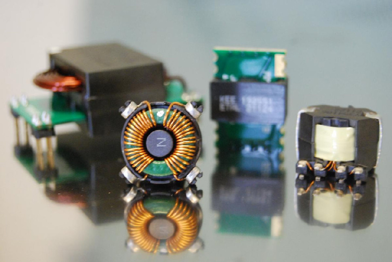
Figure 3 - Nanocrystalline common-mode chokes provide damping of noise frequency over a wider frequency range
Why wire is important
Another development facilitating smaller form factors is the introduction of triple insulated wire. This allows windings to be laid on top of each other, giving mains isolation in a smaller form factor. This technique meets all the leading international safety codes and enables transformers to be manufactured to meet safety isolation standards without the need for margins and tape barriers. With conductor diameters ranging from 0.2 mm to 1 mm, the increased winding space permits smaller transformers to be designed and reduces manufacturing time and cost.
Click image to enlarge
Figure 4 - Advanced design and innovative materials bring new possibilities for custom magnetic components
The bottom line
Innovations in design and materials enable manufacturers to quickly develop magnetic components that are perfectly suited to their task. More power capability in smaller packages is available, whatever the application.