Author:
Zhongming Ye, Analog Devices, Inc.
Date
05/03/2021
 PDF
PDF
Click image to enlarge
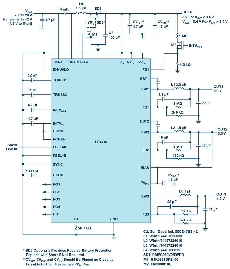
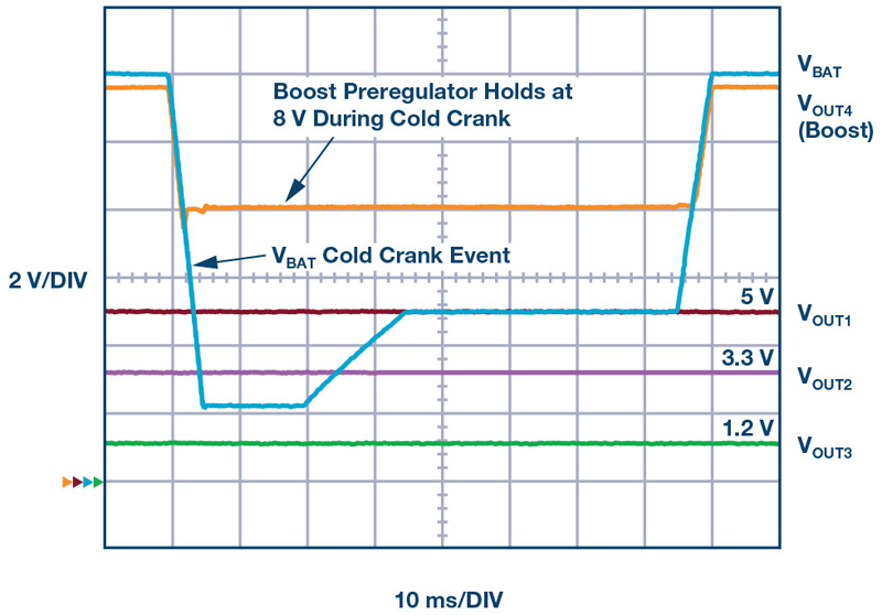
Figures 1: Cold crank-tolerant automotive supply with three regulated outputs. Three bucks are powered with a boost preregulator (VOUT4), yielding precise regulation for all three outputs through a VBAT cold crank event (also shown)
Automobiles present space-constrained, harsh environments that demand reliable and compact power supplies for increasingly complex electronics systems. The LT8603 compact regulator is a robust solution that combines two high voltage 2.5 A and 1.5 A buck regulators, a low voltage 1.8 A buck regulator, and a boost controller in a compact 6 mm × 6 mm QFN package. The boost controller simplifies the design of wide input, multiple output supplies when used, for example, in the following solutions:
Cold Crank-Tolerant Automotive Supply with Three Regulated Outputs
In automobile applications, regulated 5 V, 3.3 V, and sub-2 V rails are required to power various analog and digital ICs that may require different rails for content, the processor I/O, and the core. These rails are generated from the nominal 12 V automotive battery voltage VBAT, which typically ranges from 8 V to 16 V. High efficiency step-down buck regulators cover most situations, but VBAT can drop to 2V for 10s of ms during a cold crank situation, where pure buck regulators would lose regulation if powered directly from VBAT.
The LT8603 boost controller operates down to 2 V, making it ideal as a preregulator to power the buck regulators. When VBAT drops below 8.5 V, the boost controller output (OUT4) is regulated to 8V. The two high voltage bucks can ride through the cold crank condition while providing constant 5 V and 3.3 V outputs, as shown in Figure 1. Once VBAT recovers to above 8V from the cold crank, the boost controller simply works as diode through. The high voltage bucks can handle VBAT up to 42 V. In Figure 1, the low voltage buck is powered from OUT2, providing 1.2 V through the cold crank event.
Click image to enlarge
Figures 1a & 1b:. Cold crank-tolerant automotive supply with three regulated outputs. Three bucks are powered with a boost preregulator (VOUT4), yielding precise regulation for all three outputs through a VBAT cold crank event (also shown)
Four Regulated Outputs with the Fourth Rail as SEPIC
VBAT can remain high for an extended period of time, such as during a double battery jump-start or in a 24 V system. This has no effect on the boost regulator in Figure 1—VBAT passes through when VBAT is higher than 8 V—but the current output capacities of the two high voltage buck regulators are typically thermally limited at higher VBAT due to increased switching losses, especially at 2 MHz switching frequency that is often used in automotive applications.
The temperature rise can be controlled by either reducing the switching frequency or reducing the operating voltage of the buck regulators. In Figure 2, the fourth channel is set up as a SEPIC to power the high voltage bucks, with its output regulated at 12 V, which is optimal for the buck regulator efficiency. By running the bucks at optimal efficiency, the temperature rise is well controlled. Figure 2 shows an easy way togenerate four accurately regulated outputs. At light load, this circuit maintains regulations with input down to 2V.

Click image to enlarge
Figure 2. High voltage bucks optimized for efficiency and powered by a SEPIC
Boost Powered from One of the Bucks
Some automotive applications require a regulated high voltage, such as 54 V. One way to produce this regulated high voltage rail is to drive the boost regulator from the output of one of the high voltage buck regulators, as shown in Figure 3. All four outputs are regulated as long as VBAT is higher than the minimum input voltage of the high voltage bucks. The buck regulator limits the maximum current of the boost converter, protecting the boost against short circuits and limiting cycle-by-cycle current.

Click image to enlarge
Figure 3. Four regulated outputs with the boost converter are powered from the Channel 3 buck regulator
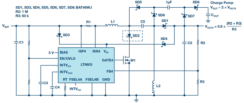
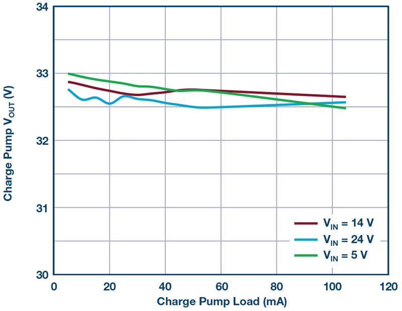
Additional Regulated Voltage with Charge Pump
A charge pump circuit can be added to a SEPIC circuit, as shown in Figure 4, to provide another regulated output. The regulation curves are shown in Figure 4 for different input voltages. Similarly, a negative output charge pump can be implemented to generate a negative rail.
Click image to enlarge
Click image to enlarge
Figures 4a & 4b: A charge pump circuit provides an additional high voltage output.
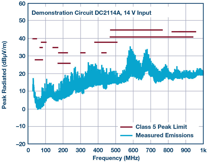
EMI Performance
The LT8603 uses a 2-phase clock. Channel 1 operates 180° from Channel 2, reducing the peak input current of the bucks and helping reduce EMI. The high density of electronic components requires carefully balancing of thermal and EMI performance. The LT8603 demo circuit DC2114A exemplifies a layout optimized for low EMI, passing CISPR25 Class 5 peak limits. Figure 5 shows the radiated EMI results with vertical polarization in the range of 30MHz to 1000MHz. Input is 14V with a 1A load in each of the outputs.
Click image to enlarge
Figure 5. LT8603 DC2114A CISPR 25 Class 5 radiated EMI, 30 MHz to 1 GHz.
Conclusion
The LT8603 offers versatile and compact power supply solutions by combining three buck regulators and a boost controller into a tiny 6mm × 6mm QFN package. Each of the buck regulators has internal power switches, cycle-by-cycle current limiting, and track/soft start control. Its synchronous rectification topology delivers up to 94% efficiency. Burst Mode operation keeps quiescent current under 30µA (all channels on), ideal for always-on systems. The wide input range, from 2V to 42V, and versatile functions make the LT8603 a good fit for automotive and other demanding applications.
 - small.jpg)