The Renesas RZ/N1 family, offer high-precision time sync and time-controlled transmission using TDMA
Extensions to the IEEE 802.1Q standard for Ethernet switching, listed under the generic term "Time Sensitive Networking" (TSN), allow automation solutions with homogeneous network architecture from sensors to the cloud. In contrast to this, traditional solutions using proprietary network standards at the field level to ensure hard real-time always mean a certain discontinuity in the network architecture. The TSN technology resolves this discontinuity, facilitating the flow of information between the field level and higher levels of automation hierarchy. In addition, users and equipment manufacturers also benefit from a unified hardware that offers flexibility and cost savings. Another plus point is a better utilisation of installed equipment and cables through common use for a wide variety of applications without risking mutual interference.
Due to the apparent benefits mentioned above, the introduction of TSN technology into the automation world is no longer questioned today. Strategy variations are found mostly regarding timing and sequence of steps only. Individual manufacturers already have the first TSN capable products on the market today, more are committed, and others will follow step by step.
A key question while introducing new technologies is the broad availability of suitable hardware. The TSN standards are still relatively new, and the implementation into corresponding semiconductor devices requires time. On the other hand, only a small however essential part of the TSN standards requires dedicated hardware support. Many TSN-related functions, e.g. for network management, are purely software-based and can easily be implemented on any hardware.
Today, equipment manufacturers have two main options at their disposal to map TSN functionality in their equipment. On the one hand, FPGA-based network interfaces offer a flexible approach to incorporate latest functions into products promptly. The price for this cumulates over three factors, i.e., the relatively high product costs, the development efforts for the FPGA logic including testing, certification and eventually the IP licensing costs.
On the other hand, the market offers standard semiconductors that provide verified TSN functions at low cost. This is feasible because instead of reinventing the wheel, the TSN standards, which are largely based on proven concepts, develop and generalise these concepts further. Depending on the specific application requirements, using these TSN precursor devices, it is already possible and common practice today to implement the TSN functionality in automation solutions based on off-the-shelf standard components.
TSN technology for an automation system
The demands on network elements, in particular on end nodes and switches, vary depending on their function and configuration in the network. The network interface of a PLC or in an edge computer must be more efficient than that of simple field device. Likewise, the switches at this level must also cope with a much higher network load than their counterparts in a line at the lower end of the field level. This is reflected in the minimum requirements for the corresponding components so that especially in the area of simple field components, simplified solutions for line or ring topologies are feasible with only two external Ethernet ports.
The TSN sub-standard family offers two main methods for chronologically deterministic transmission: Prioritisation and frame pre-emption (asynchronous) and time-controlled transmission in reserved time slots (TDMA method, synchronous). Both can also be used in combination. Currently, in the field of industrial automation, the focus is on the time-controlled transmission of hard real-time data via TSN. This principle has already proven itself in established standards such as Profinet IRT, SERCOS III, EtherCAT or Powerlink. The TSN standard IEEE802.1Qbv extends and generalises the existing proprietary mechanisms to extend their scope of application and enable the coexistence of different real-time systems in a common network domain without mutual interaction. The time-controlled transmission to Qbv avoids undesired collisions between different data streams leaving the switch at a common port. If the component under discussion is only an end node with a single Ethernet port, i. e. without integrated switch functionality for forwarding, then a sufficiently precise control of the transmission time of individual Ethernet frames is adequate for participation in time-controlled TSN communication.
A precise time synchronisation of all participating network components with sub-microsecond accuracy is a necessary prerequisite for the effective use of time-controlled transmission. The established procedures in accordance with IEEE1588 and IEEE802.1AS place the same requirements on the hardware. Corresponding devices must have a PTP hardware timer from which time stamps are derived while sending and receiving time synchronisation messages. The frequency and phase of the PTP timer must be adjustable by time synchronisation.
TSN in existing devices
Some of the currently available semiconductor devices, such as those of the Renesas RZ/N1 family, already offer mechanisms like high-precision time synchronisation and time-controlled transmission using the TDMA method.
TSN will utilize the new IEEE 802.1AS-Rev protocol which is based on IEEE 1588 and does not impose any additional requirements on the hardware. As an alternative today either its precursor, the IEEE 802.1AS or the IEEE 1588, which was being used hitherto, is deployed. Differences between the implementation of the two lie exclusively in the software layers.
The TDMA technique has also already been implemented in available chips as an extension of the Qav specification. In this case, the Ethernet frames are classified according to Qav in order to assign them to individual time slots within a transmission cycle. This mechanism is the predecessor of the TSN sub-standard Qbv. A chip with 1588/.1AS support and Qav + TDMA is suitable to realise a simplified Qbv TSN-functionality. This makes it possible to exploit the advantages of TSN technology at field level in simple end nodes for star wiring as well as for line or ring topologies and mixed forms.
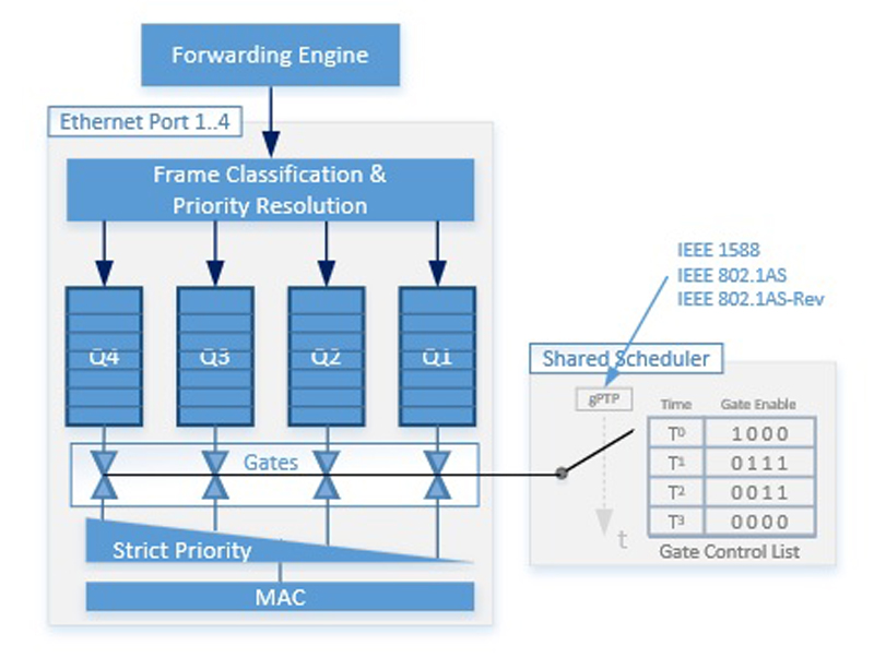
Figure 1 shows the structure of the TDMA function in the RZ/N1 blocks. At the top end, the incoming Ethernet frames are relayed to their destination ports by the forwarding engine. There, each frame is classified according to configurable criteria and placed in one of the four output queues (Queues). The gPTP hardware timer is synchronised with the network time of the TSN domain. All time slots of the TDMA mechanism are derived from it. The time slots with individually configurable length are specified centrally for all Ethernet ports of the device in a Gate Control List with four entries.
Controlled via Bitmasks, arbitrary output port queues can be opened in each time slot. In this context, “opened” means that Ethernet frames, which are in a queue, can reach the MAC and thus the cable via priority control. The priority control always selects the Ethernet frame of the highest priority open queue for forwarding. However, the Ethernet frames in the “closed” queues are not forwarded in the relevant time slot.
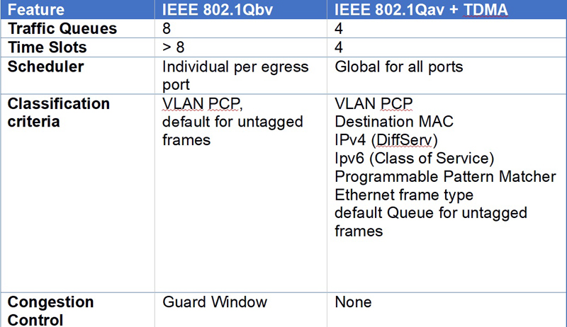
The differences in Qbv-capable hardware lie primarily in the number of different queues and time slots, i. e. the diversification in the handling of individual Ethernet frames. Table 1 shows a detailed comparison. For example, the Renesas RZ/N1 family chips support four queues and four time slots. For comparison: the TSN standard Qbv defines eight queues and leaves the number of time slots undefined. Apart from that, though a Qbv-standard switch has a central gPTP timer, the Gate Control List is port specific so that each port of the switch can have an individual schedule.
Table 1. Comparison between Qbv and Qav +TDMA
Click image to enlarge
For a field device with a single Ethernet port and field devices in a simple line or ring topology using the embedded switch, the above limitations are often acceptable. This is so because only a few different real-time streams have to be transmitted, and the transmission schedule for all ports is identical to allow an unobstructed flow of the Ethernet frames through the component and thus through the line or ring. The following TSN application example illustrates this.
TSN application example
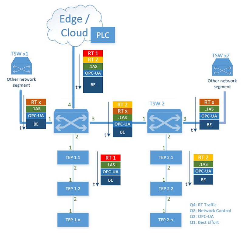
The sample configuration in Figure 2 illustrates how a TSN-based automation solution can be built using the features of the available RZ/N1 devices.
Click image to enlarge
Figure 2. TSN sample system
A TSN-capable PLC, existent physically in the plant or virtually in an edge computer, controls a large number of I/O components (TEP n.m) that are organised in two lines. As an alternative, a ring structure would also be possible here. The network traffic is time-controlled and synchronised with the PLC's operational cycles. The PLC operational cycles consist of three phases: Reading the actual values from the I/O devices, calculating new output values through the PLC program and output the new output values to the terminal devices. Over the time, phase 1 and phase 3 overlap. The TSN backbone consisting of TSN switches TSW 1 and TSW 2 must handle all network traffic between PLC and sub-rings and, if necessary, also as indicated by the TSW x1 and TSW x2 switches, further cross-traffic between network components connected to the segment under review. This calls for full support of the TSN standards Qbv and, if required, Qbu by the TSW 1 and TSW 2 backbone switches.
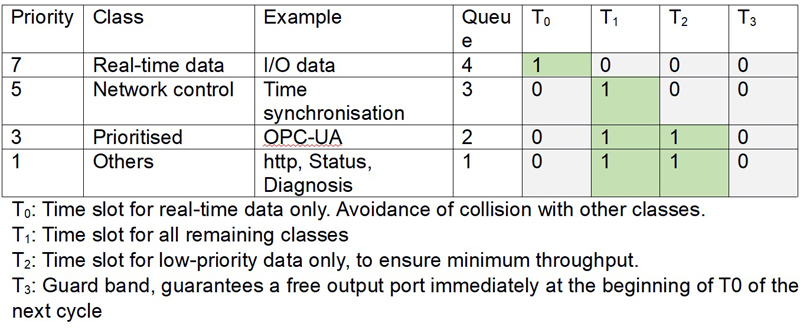
The requirements in the sub-lines are much more relaxed. The TEP n.m components there must only forward network traffic to and from the neighbouring components. Their role as a TSN endpoint is limited to a single real-time stream in the transmitting and receiving direction for communication with the PLC and other non-time-critical communication, e. g. for time synchronisation or as an OPC-UA server. Table 2 in this example shows the different classes and their mapping to the available hardware of the RZ/N1 family devices which fulfill all requirements of the TSN function required in this constellation.
Table 2. Communication classes of the sample network
Click image to enlarge
T0: Time slot for real-time data only. Avoidance of collision with other classes.
T1: Time slot for all remaining classes
T2: Time slot for low-priority data only, to ensure minimum throughput.
T3: Guard band, guarantees a free output port immediately at the beginning of T0 of the next cycle
In the example, all network components, switches, and end nodes are synchronised with each other via the IEEE 802.1AS time synchronisation protocol and use the time-controlled transmission to avoid undesired collisions. Communication takes place in a fixed time raster which repeats cyclically. The assignment of the classes to the time slots of this raster for devices in the sub-lines is also shown in table 2. The cycle time and the length of the individual time slots depend on the application. The time slot T3 is always empty, i. e. no queue may send during this time, and should have the length of the longest occurring Ethernet frame. This guarantees that the output ports at the beginning of the real-time window T0 are always free and are not occupied by the previous frame, which would have led to an undesired delay while sending the real-time frame.
Communication scheme
All TEP n.m endpoints send their actual values as input variables to the PLC at the beginning of each network cycle. The PLC for its part sends the new output values computed in the last cycle to the endpoints.
For this purpose, on each line and the backbone, a time slot T0 is reserved during which only real-time data is transferred between the endpoints TEP n.m and the PLC. Collisions with other network traffic are impossible so that the maximum transmission time to and from each endpoint is guaranteed. The end nodes transmit their actual values to their superordinate backbone switches TSW1 and TSW 2 in both lines simultaneously. These collect the data and send it to the PLC. Also here, collisions between the line frames are excluded because the backbone switches transmit the data of each line in a separate time slot. This necessitates appropriate resources in the backbone switches.
The output values are transmitted in two steps to achieve utmost simultaneous arrival of the PLC output values at each of the TEP n.m end node; first, to the line 2, which is one switch away, then to line 1. The time slot T0 in the sub-lines must be selected long enough to provide sufficient time for forwarding all output variables. The simultaneous exchange of actual and new output values runs collision free and doesn’t require any additional measures because the data flow in opposite directions.
After all actual values have reached the PLC within their defined transmission window, and the new output values have arrived at all end nodes, the PLC starts to process its user program which computes new output values from the current values.
The output nodes process their new set-points synchronously based on the network-wide synchronised time so that all components change their output states simultaneously.

Click image to enlarge
Figure 3. TSN Schedule
After the PLC has completed its computations, the next network cycle follows seamlessly.
Additional data can be transferred beyond the reserved time slots on the TSN backbone and in the lines one and two without having to worry about any effect on the real-time system in operation. For example, real-time data RT x can be encapsulated between adjacent network segments in individual time slots as long as the total data throughput of the individual network strands provides sufficient remaining bandwidth. Additional important data streams are used for time synchronisation or to query OPC-UA objects.
Conclusion
TSN is still a young standard, and the establishment of the necessary hardware support is in progress now. But even with off-the-shelf standard components such as those of the Renesas RZ/N1 product family, which are based on extended predecessor standards, the benefits of TSN technology can already be reaped today as long as the differences are acceptable in the actual application.
Renesas Electronics Europe


