Understanding power factor and the need for power factor correction
Due to international legislation governing power factor and harmonic distortion, PFC is now a serious industry concern
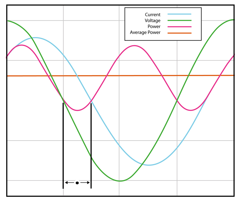
Figure 1: An ideal waveform with a power factor of 0
Until the era of switching power supplies, Power Factor - and power factor correction - wasn't a big concern for all but a handful of electrical engineers working with large electric motors, and other, generally high-power and industrial, electric loads. Now, thanks to international legislation governing power factor and harmonic distortion, this subject is high on the list of concerns for many engineers designing systems for global use. A Quick Introduction to Power Factor Power factor (pf) is the ratio between real power (P) flowing to the load, and the apparent power in the circuit (S): pf = P/S. It is a sinusoidal waveform and therefore expressed as a dimensionless number between -1 and 1. Real power is measured in watts (W) and apparent power in volt-amps (VA). For a purely resistive load, the two figures are identical; for a reactive load the arithmetic for the apparent power produces the same figure, that is, the product of the RMS values of voltage and current. However, to find the actual (real) power delivered to the load, the instantaneous product of voltage and current must be integrated over the complete sine-wave cycle (see Figure 1).
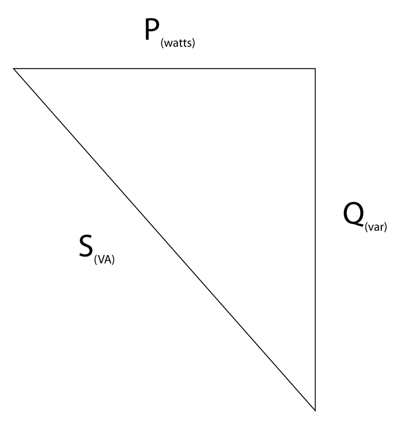
When current is leading or lagging voltage, the value of that integral will always be less than the value for the in-phase case over the same interval. This reflects the attribute of an inductor or a capacitor to act as an energy store; at various points through the AC cycle the reactive component is either storing energy, or returning it to the system. The apparent power is the vector sum of the true power and the reactive power (Q), measured in reactive volt amperes (var); conventionally, this relationship is expressed as: P = S cos? or P2+Q2=S2 The relationship is conventionally visualized in a right-angled triangle vector diagram (see Figure 2). This is a basic definition and works for pure sinusoids; non-sinusoidal waveforms are more complex, but can be represented by a series of harmonic sinusoids and therefore the same basic principles apply.
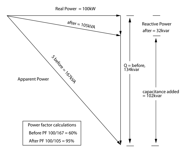
The Implications Power supply utilities and generating bodies require their customers to present a load to the power grid that is as near to unity power factor as possible. The main, but not the only reason, is fiscal. The customer expects to pay for the "real" work done on his premises - in other words, the value of W, above. Electric utilities must provision to deliver the peak voltage and current values in the waveform at any time. A power factor of less than one is effectively an increase in their costs, and one that they pass back to customers by imposing an increased tariff for customers with low power factor loads. Achieving maximum power factor is therefore a "win-win" for all concerned. There are further effects that power generators must contend with that make a unity-power-factor load highly preferable. Rotating plant generating power is more difficult to manage and to keep stable when supplying a low power factor, and there can be heating or overload hazards for transformers and transmission equipment in the supply grid; grid stability is also more difficult to maintain with low-power-factor loads attached to the system. Low power factor also tends to be associated with other negative attributes for a well-behaved electrical load. Highly-distorted current waveforms drawn from the mains can inject high-order harmonics back into the supply grid (see Figure 3). Transmission equipment has higher losses at higher frequencies leading to heating problems; if the higher frequencies are present in the load placed directly on the generating plant, they can manifest themselves as destructive vibrations leading to excessive wear on components such as bearings. Current distortion can lead to out-of-balance currents in the neutral lines of 3-phase distribution networks, which in turn can take the neutral away from ground (voltage) and give rise to a multiplicity of problems. The first attempt to legislate for mains power interference came over 100 years ago, in 1899, to prevent incandescent lamps from flickering, but one of the key regulations came in 1978, with IEC 555-2 requiring power factor correction be incorporated into consumer products. More stringent legislation is being enacted around the world. For example, the EU currently legislates EN61000-3-2 for equipment that implements a power supply with a rating between 75 and 600 W. This sets limits to the 39th harmonic for equipment with input currents less than or equal to 16 A per phase. Split into four classes, A, B, C (for appliances, power tools, and lighting) and the most stringent class, D (for computer monitors and TVs), similar regulations have been implemented in China, Japan, and Australia. Although the US does not have the same level of legislation as the European Union, the Energy Star program operated by the US Department of Energy, as well as schemes such as 80 PLUS for computer and data-center power systems, are placing increasing emphasis on maintaining a high power factor; calling for a power factor of 0.9 or higher at 100 percent of rated output in the system's power supply. Power Supplies for Electronic Systems Even when most electronic equipment was supplied by power supplies that used linear regulation, power factor (and waveform distortion) was often less than ideal, but was rarely addressed for anything other than the largest supplies. The typical, conventional off-line arrangement was that of a transformer followed by a bridge rectifier, feeding a reservoir capacitor. Conduction through the rectifier would take place when the DC voltage on the output line had sagged below the instantaneous value of the transformed AC supply, which could be for the complete cycle at full load, or only at the peak of the AC waveform under light load. Switching power supplies can significantly worsen the situation. The off-line part of the design may not change, still comprising a transformer/rectifier and capacitor, but now feeding one or more switching regulators. The input rectifier continues to generate poorly-shaped current waveforms, but now with the added burden that some of the higher-frequency switching noise from the regulation stage can find its way back into current drawn from the wall socket. Not only does this shift the effective current peak away from that of the voltage waveform in time, it also introduces high-harmonic-content switching waveforms that potentially worsen the distortion of the current waveform. The arrival of this class of supply broadly coincided with the widespread deployment of PCs and other IT products in great numbers. Such trends led directly to today's legislative environment.
Power Factor Correction The solution to excess harmonics is to use power factor correction (PFC). This shapes the input current of the power supply to maximize the real power level from the mains and minimize harmonic distortion (see Figure 4). Ideally, the electrical appliance should present a load that resembles a linear load, such as a simple resistor, rather than the reactive load of an uncorrected switching power supply. This corrected waveform minimizes losses as well as interference with other devices being powered from the same source. Compensation for low power factor can be by passive or active devices. The simplest case is highlighted in electric motor applications. Naturally, as wound machines, they provide a highly inductive load, and adding capacitors to the supply network has long been standard practice. However, even this case may not be entirely simple. For example, the designer of such a network has to take care not to create unwanted resonant effects. Variable power factor in the load may be accommodated by an adaptive scheme to connect reactive elements as required and in high-power contexts (MW scale) rotating-machinery solutions can be applied.
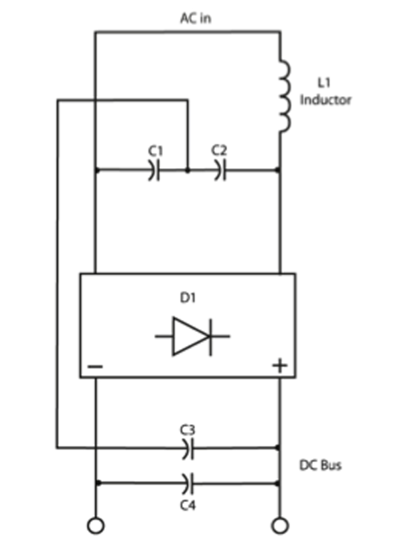
Passive power factor correction in the form of filtering can be effective, within limits, and has the effect of reducing the higher-order current harmonics that, as noted above, contribute to degraded power factor. Such techniques involve putting a low-pass filter in the input side of the power supply to suppress higher-order harmonic components, and then compensating lead/lag characteristics as with conventional power factor. The downside to a passive PFC design is that large (both by value, and physically) inductors and/or capacitors may be required. Additionally, there are limitations to the input range and power rating when implementing this scheme (see Figure 5). Passive PFC circuits are generally able to achieve a power factor in the range of 0.70-0.75. The existence of, and rapid progress in, high-speed, high-current capacity semiconductor switches now make available the option to achieve a power factor up to 0.99. Active power factor correction is the scheme that is most widely applied in present-day designs. A switching pre-regulator stage is placed in the input current path of the supply. That regulator is designed not only to maintain a constant DC voltage to feed the main converter stage of the power supply, but also to draw current from the input in-phase with the incoming AC voltage waveform. And while adding a switching stage does impose some extra losses, and some extra cost, there are compensating savings in the form of smaller passive filtering components, and in the supply's main converter. Summary Power factor is on the list of concerns for designers of virtually every device that draws significant power from a mains socket, as well as for engineers in heavy-electrical sectors. The power factor target, based on legislation, plus efficiency, component cost, and volume/board space, needs to be considered. CUI