Urban Legends about Thermal Interface Materials
Proper thermal design in power electronics is critical to device performance
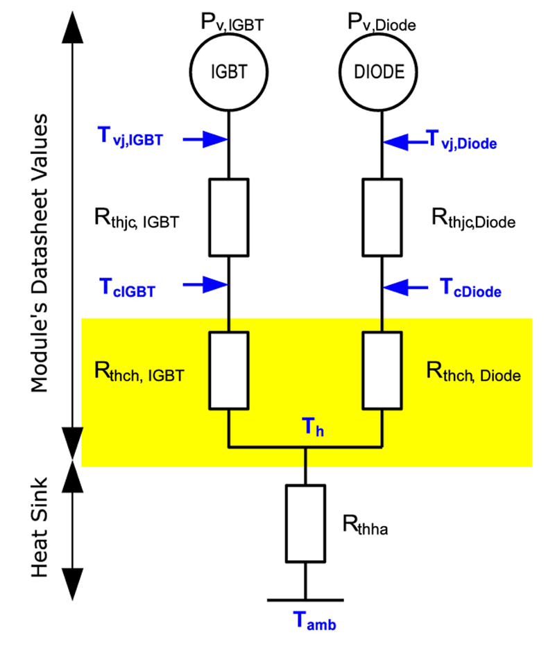
Figure 1: Simplified thermal model using datasheet values. The thermal interface material is hidden inside the yellow area
Proper thermal design in power electronics is the necessary fundamental to ensure that the final application will operate throughout the predicted lifetime. Thus, it remains a key element in the design process. Thermal transfer, including the thermal interface materials (TIM) is the core of power electronic systems. Inadequate handling of these materials or inaccuracies during the design phase can lead to fatal consequences when operating the equipment. Whenever new developments or optimizations of existing designs are ongoing, the developer has to consider what power semiconductor to combine with a certain heat sink. The thermal interface material, connecting the semiconductor to the heat sink, usually is not a major consideration. Most often, materials are in use simply because they have been there for years; what was ok for the last decade cannot be wrong today. This however is the first misjudgment. Just like semiconductors, thermal interface materials have been significantly enhanced over the last several years. When the developer searches for alternative materials, he is facing a nearly unmanageable variety of possible candidates. This leads to the question of how to evaluate and compare the different materials. The myth about datasheet values After extensive research and collecting the data for possible alternatives, the developer takes a well known approach: Take the datasheet given by the manufacturer, compare different materials in regards of thermal conductivity and start a simulation to estimate chip temperatures. A typical scenario usually consists of - The maximum ambient temperature expected - The known thermal resistances connecting the chip to the module's base plate RthJC - The heat sink's thermal resistance to ambient RthHA determined through measurement - The thermal conductivity of a homogenous layer of grease as described in the datasheet - Most likely, the semiconductor's manufacturer added to the datasheet a typical resistance base plate to heat sink R,sub>thCH assuming a common grease is in use This leads to a simplified thermal model as given in figure 1. In case the losses Pv generated are known exactly, the chip temperature results from bare math.
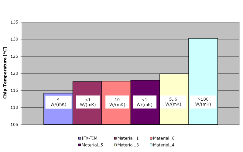
The lack of accuracy of such simplified models becomes obvious if the calculated results are compared to measured data. In our case the test bench was designed dedicated to measuring the effectiveness of thermal interface materials. Screen printing was used to apply thermal greases to power modules that were then mounted to heat sinks. The setup consisted of six identical units and provided an insight to chip temperature development throughout an eight month test period. It was expected that the thermal interface with the highest conductivity would achieve the lowest chip temperature and in turn the longest life time. Throughout the eight months test, daily measurement of the maximum chip temperatures was recorded. As the final result, the average value of these measured temperatures is considered. Figure 2 summarizes the stress test that was conducted for more than 100.000 cycles. The diagram clearly shows that there is no correlation at all between the chip temperature achieved in the test and the datasheet value given for thermal conductivity. The material with the highest conductivity leads to the worst result. At the same time, materials that deviate by a factor 10 in conductivity achieved similar chip temperatures. Comparing and evaluating the thermal quality of thermal grease purely based on datasheet values is futile. What's causing this dilemma is the way the datasheet value is determined. The test setup described in the standard ASTM5470-12 features properties that are incompatible to power semiconductors. It is rather suitable to describe the situation found in discrete parts or processors. Surface structures and mounting forces coming from screws are disregarded, just like the fact that a noteworthy portion of heat is transferred by metal-to-metal contact especially in the area the screws are located in. Further important parameters, like flow characteristics and wetting abilities of interface materials, are either missing in the description or are very difficult to pinpoint within comparable numbers. The developer is left with one possibility only; copious in-situ tests of the material under consideration in a particular application.
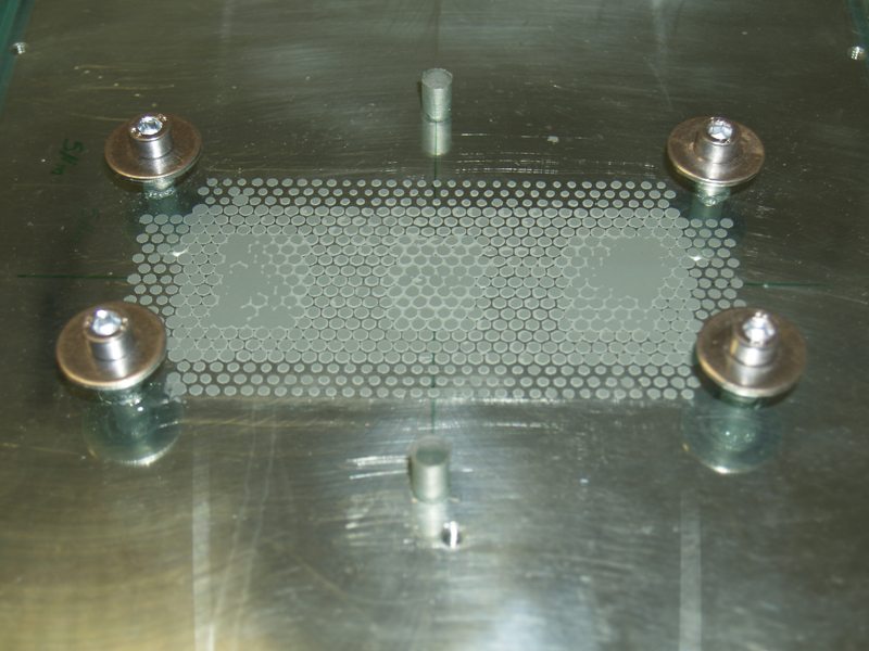
The Glass Pane Saga A recurring experiment consists of mounting a module with thermal grease applied to a glass pane to observe the way the material spreads inside the setup. What appears to be a clever idea in first place turns out to be highly questionable as no knowledge regarding thermal qualities can be derived from this attempt. A glass pane does not feature the microscopic channels that are common to heat sinks with a milled surface. However, it is this structure that enhances the flow characteristics of paste-like greases. Therefore the view through a glass pane leads to dubious statements. Instead of mounting a module to a glass pane, the glass can be mounted to a heat sink with thermal grease in between. Though the heat sink now provides the microscopic structure, the glass does not feature the cavities found in power modules. This configuration too does not generate a reliable statement regarding the flow characteristics of thermal greases. Figure 3 is a photo taken from such a setup. The photo clearly shows that, due to the planar surface, the glass applies homogeneous pressure even in cold condition. This behavior is different compared to what is seen using a power module. Starting at room temperature, the setup shams a wrong impression that gets even worse if higher temperatures would be considered. The base plate of power modules changes in shape at elevated temperature levels due to bimetallic effects. As it lowers towards the heat sink, it applies large mechanical forces to the thermal interface material applied and in turn to the heat sink. Heating up the module mounted to the glass pane is not a viable option, as the glass cannot withstand the thermal or mechanical stress and would be destroyed during the test. Thus, it can be concluded that the experiment is not capable to simulate the behavior of the real application and therefore is of no relevance.
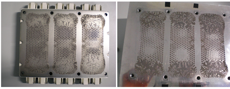
The Imprint Legend An evenly delusive idea is the art of interpreting imprints. A power electronic system, consisting of module, grease and heat sink, is operated for a certain time and disassembled afterwards. The remaining imprints on module and heat sink are taken as a hint for the thermal quality of the tested material. This approach represents guessing the properties of an assembled structure, usually operating at high temperature and under high pressure, by looking at the disassembled components at room temperature. It is self-evident, that this approach will not lead to credible statements. The picture of the imprint on an EconoPACK + as shown in figure 4 may be used as an example. The usual interpretation of such an imprint would come up with findings regarding the poor spreading of the grease, obviously caused by too little material being applied, concluding that the thermal transfer clearly was disastrous. The measurement of the actual chip temperature during the test was done using an IR-Camera. In contradiction to the interpretation, the thermal transfer was excellent as no other material in the test achieved similarly low chip temperatures. Many things regarding thermal interface materials a rather believed in than measured. There is only one important parameter - the chip temperature - and the advice can only be to observe this parameter as closely and accurately as possible. Infineon Technologies


