USB-C Power Delivery Data Lines Demand Enhanced Protection
USB Type-C brings new challenges in interconnecting, powering, and protecting our electronic gadgets such as digital cameras and ultra-thin tablets.
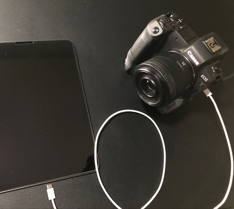
Figure 1: A digital camera connected to a tablet via a USB-C cable
USB-C and USB-C power delivery raise voltage and power levels. A new reversible connector with tighter pin pitch than that of USB Micro-B, increases the risk of short circuits. This, in conjunction with the ever-increasing complexity of portable devices leads to enhanced ESD, surge and overvoltage protection requirements. In this design solution we propose a compact, fully featured protection IC that can lead to a dramatically lower BOM and smaller PCB space occupancy.
The new USB Type-C (USB-C) cable and connector specification is dramatically simplifying the way we interconnect and power our electronic gadgets such as digital cameras and ultra-thin tablets (Figure 1). The specification supports USB-C charging applications up to 15W, and the USB-C power delivery (PD), which extends charging up to 100W, includes a wide variety of different devices that can be interchangeably charged. With USB Type-C come new challenges in protecting the system. The new connector has a smaller pitch than that of the USB Micro-B, which leads to increased risk of mechanical shorts to VBUS. Additionally, due to the high voltages associated with USB PD, more robust protections are needed. And finally, the ever-increasing complexity of the electronic loads demand enhanced protection from ESD and voltage surges. This design solution reviews the USB Type-C PD architecture and the challenges associated with D+/D- data signal protection. It then proposes a highly integrated 2 x SPDT switch that can address these challenges with minimum BOM and PCB occupancy.
USB-C PD system
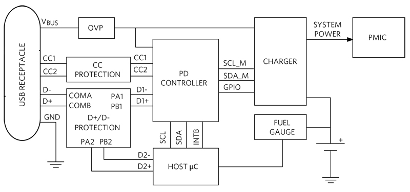
Figure 2 illustrates a typical portable power management device front-end equipped to connect to a USB-C cable and powered by a lithium-ion (Li+) battery.
Click image to enlarge
Figure 2: USB PD power management system
When the VBUS is present, it powers the charger, the system, and the rest of the blocks. In this phase, the battery is charged. When the VBUS is disconnected, the battery powers the system. With the USB-C cable, the CC1 and CC2 pins determine port connection, cable orientation, role detection, and port control. The D+/D- lines are the standard USB-C communication lines handling data with a speed of 480Mbps and are protected by the D+/D- protection device. The PD controller implements the power deliver protocol.
The protection challenge
Electric surges and electrostatic discharges (ESDs) in a power supply are common and can interfere with or cause damage of electronic loads and equipment. ESD is caused by the transfer of static electrical charge from a body to an electronic circuit and is a big concern for handheld electronics. Surges can be caused by lightning or induced in long cables laying in proximity of a lightning strike. Switches or relays can cause surges during on and off operation. And a load dump is a surge generated by cutting the battery connection off on an automobile. A good data line protection IC should offer adequate protection without significant data degradation.
Integrated solution
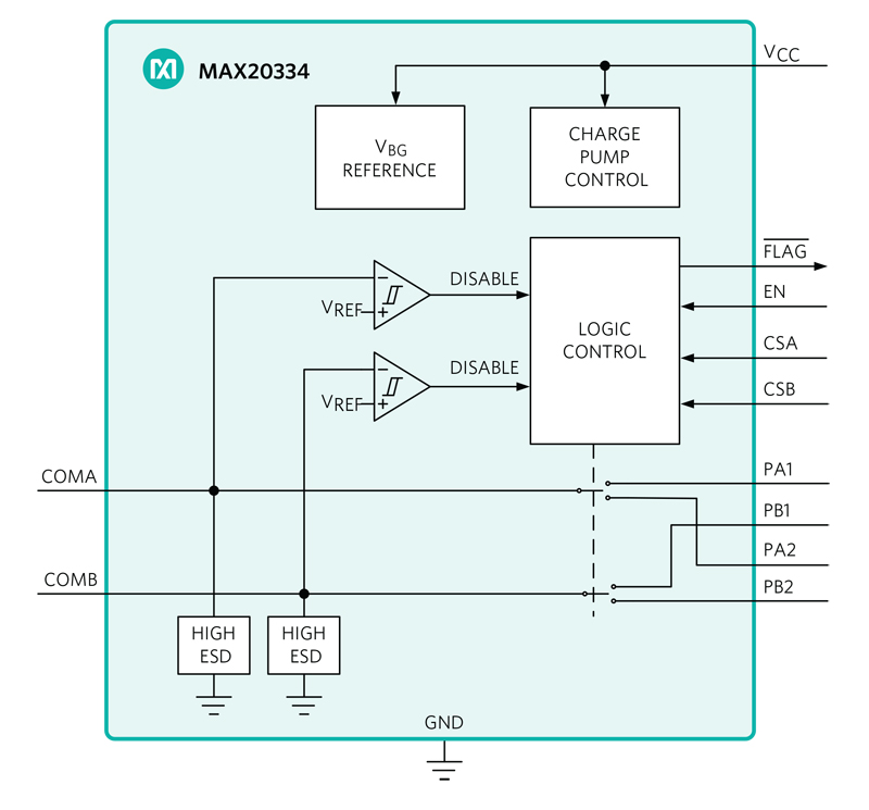
As an example, the MAX20334 is a 2 x SPDT switch with overvoltage protection intended for use with portable devices (Figure 3). The IC is designed to protect the downstream data line from a high-voltage short, ESD, or surge event. The device combines low on-capacitance and low on-resistance necessary for high-performance switching applications in portable electronics. The IC features internal positive overvoltage and surge protection. The device handles USB low/full/high-speed signaling and operates from a 2.7V to 5.5V supply. The IC is available in a 12-bump (1.23mm x 1.63mm) wafer-level package (WLP) and operates over the -40°C to +85°C extended temperature range.
Click image to enlarge
Figure 3: 2 x SPDT switch with extended protection
Extended protection
ESD protection structures are incorporated on all pins to protect against electrostatic discharges up to ±2kV (Human Body Model) encountered during handling and assembly. COMA and COMB (Figures 2 and 3) are further protected against ESD up to ±15kV (Human Body Model), ±15kV (Air Gap Discharge method described in IEC 61000-4-2), and ±8kV (Contact Discharge method described in IEC61000-4-2) without damage. The ESD structures withstand high ESD, both in normal operation and when the device is powered down. After an ESD event, the IC continues to function without latch-up. The IC is surge-protected from -30V to +45V (IEC61000-4-5) and overvoltage protected up to +20.5V.
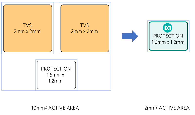
Figure 4 compares the PCB layout of this highly integrated, extended protection solution with a typical competitor device offering positive-only surge protection and lower OV and ESD protections. The latter will require additional circuitry to meet ESD/Surge/OV specifications, leading to a more costly BOM and a 5X bigger PCB active area occupancy.
Click image to enlarge
Figure 4: Extended protection advantage
Data integrity
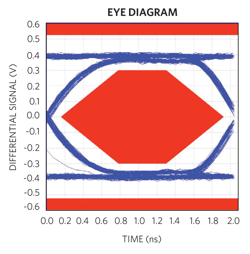
The eye diagram in Figure 5 shows at a glance the good level of integrity of the data signal, as the curved blue lines maintain close-to-maximum distance from the forbidden red zone. The high bandwidth of the protection IC causes minimum slowdown of the signal rise and fall times and jitter, resulting in a good margin for error, important to pass USB compliance tests.
Click image to enlarge
Figure 5: D+/D- eye diagram
Conclusion
With USB Type-C come new challenges in interconnecting, powering, and protecting our electronic gadgets such as digital cameras and ultra-thin tablets.The new connector has a smaller pitch than that of the USB Micro-B, leading to increased risk of mechanical shorts to VBUS. Additionally, due to the high voltages associated with USB PD, more robust protections are needed. And finally, the ever-increasing complexity of the electronic loads demand enhanced protection from ESD and voltage surges. In this design solution, we showed that an enhanced protection device with up to ±15kV ESD protection, -30V to +45V surge protection and +20.5V overvoltage protection can singlehandedly protect the data lines and, compared to less integrated devices, meet ESD/Surge/OV specifications with a lower BOM and smaller PCB active area occupancy.